Standard-ball-based laser emergent direction calibration method

A calibration method and standard ball technology, applied in the direction of using optical devices, instruments, manufacturing tools, etc., can solve the problems of cumbersome operation and no consideration of the light output direction of the sensor, etc., and achieve the effect of overcoming cumbersome operation, realizing fast solution, and improving speed

Pending Publication Date: 2020-07-03
HUAZHONG UNIV OF SCI & TECH
View PDF5 Cites 11 Cited by
  • Summary
  • Abstract
  • Description
  • Claims
  • Application Information

AI Technical Summary

Problems solved by technology

[0005] This will involve the calibration of the light emitting direction of the sensor after installation. However, many current research works do not consider the light emitting direction of the sensor. By default, the laser displacement sensor is installed on the spindle of the machine tool, and its outgoing light is parallel to the Z axis; among them, Lu Keqing et al. proposed a method for calibrating the laser light emission direction based on a multi-directional calibration block. This method constructs a quadratic equation by scanning two planes, and then obtains the laser light emission direction vector by solving the quadratic equation. However, this method obtains There are two light emitting directions, and this method needs to rotate the calibration surface to be perpendicular to the laser light emitting direction each time, and the operation is cumbersome, so how to quickly realize the light emitting direction calibration of the laser displacement sensor needs to be solved urgently

Method used


Image

  • Standard-ball-based laser emergent direction calibration method
  • Standard-ball-based laser emergent direction calibration method
  • Standard-ball-based laser emergent direction calibration method

Examples


Embodiment Construction

[0043] In order to make the object, technical solution and advantages of the present invention clearer, the present invention will be further described in detail below in conjunction with the accompanying drawings and embodiments. It should be understood that the specific embodiments described here are only used to explain the present invention, not to limit the present invention. In addition, the technical features involved in the various embodiments of the present invention described below can be combined with each other as long as they do not constitute a conflict with each other.

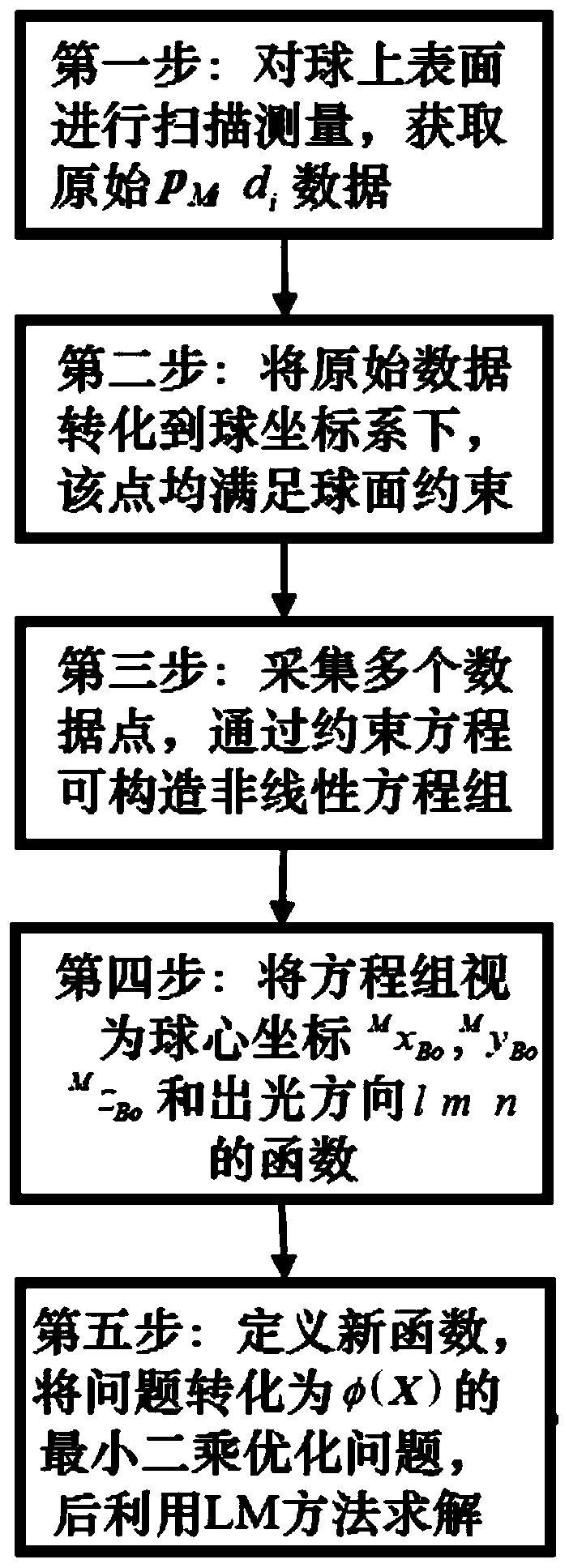
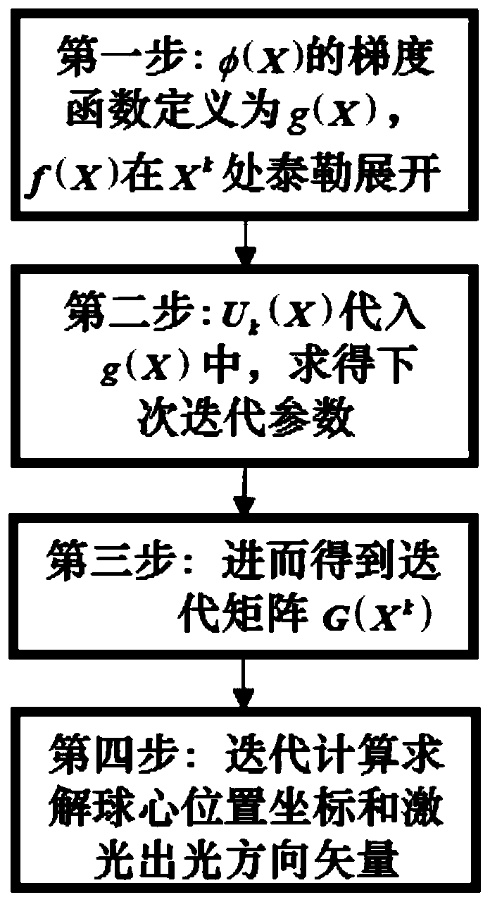
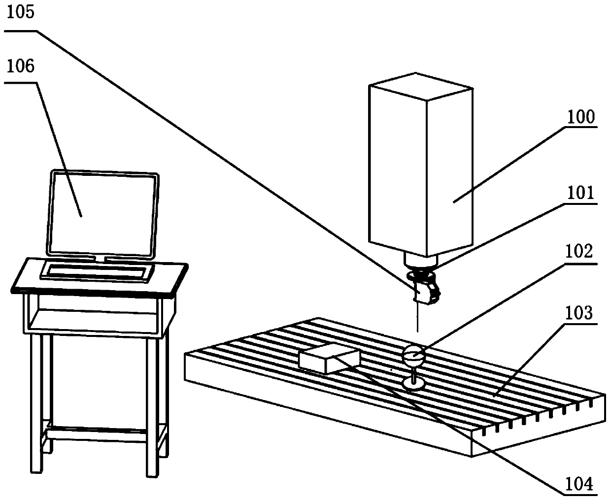
[0044] see figure 1 , figure 2 and image 3 , the method for calibrating the laser light emitting direction based on the standard sphere provided by the present invention, the calibration method mainly includes the following steps:

[0045] In step 1, the laser displacement sensor is arranged on the machine tool spindle of the machine tool, and the standard ball is fixed on the workbench of ...


PUM


Abstract

The invention belongs to the field of the online measurement related technology and discloses a standard-ball-based laser emergent direction calibration method. The method comprises the following steps of S1, installing a laser displacement sensor on a machine tool spindle, fixing a standard ball to a working platform, and driving the laser displacement sensor to conduct scanning measurement on the upper surface of the standard ball through the machine tool spindle to obtain coordinates of a machine tool and the corresponding sensor one-dimensional measuring distance value; S2, integrating obtained original data and converting the original data to a ball coordinate system, and establishing a nonlinear equation set of the ball coordinates and the laser emergent direction on the basis of theconverted data; and S3, solving and converting the nonlinear equation set to least square optimization of a new function phi(x), and solving the new function phi(x) through an Levenberg-Marquardt iterative optimization algorithm to obtain the laser emergent direction and the coordinates of the ball center. Through the standard-ball-based laser emergent direction calibration method, the efficiencyis improved, and the applicability is high.

Description

technical field [0001] The invention belongs to the technical field of on-line measurement, and more specifically, relates to a non-contact on-line measurement method, in particular to a method for calibrating the laser light emitting direction based on a standard sphere. Background technique [0002] With the rapid development of the manufacturing industry, the processing requirements for large and complex thin-walled parts such as aircraft structural parts and missile body structural parts in the aerospace field are getting higher and higher. Such parts often have many dimensions and processing features, and are easily deformed. , it is difficult to guarantee its machining accuracy. The traditional measurement method is the three-coordinate measurement method. The three-coordinate measuring instrument operates in a fully enclosed measurement environment. Its contact detection method requires cumbersome detection route design and collision simulation inspection, resulting i...

Claims


Application Information

Patent Timeline
Patent Type & Authority Applications(China)
IPC IPC(8): B23Q17/24B23Q17/22G01B11/02
CPCB23Q17/2428G01B11/02G01B21/042
Inventor 李文龙寇猛王刚
Owner HUAZHONG UNIV OF SCI & TECH
Why Eureka
Try Eureka