
Steel wire rope core conveying belt connector vulcanization electromagnetic induction heating device

An electromagnetic induction heating and steel wire rope core technology, which is applied to the field of underground wire rope core conveyor belts in mines, can solve the problems of inability to apply vulcanization processing of steel wire rope core conveyor belt joints, a large number of cylindrical coils, and complex winding structures, etc., so as to achieve energy utilization. High efficiency, low cost and small volume

Inactive Publication Date: 2020-07-03
TAIYUAN UNIV OF TECH
View PDF9 Cites 2 Cited by
  • Summary
  • Abstract
  • Description
  • Claims
  • Application Information

AI Technical Summary

Problems solved by technology

The winding structure is complex and the number is large. At the same time, the number of cylindrical coils is large, the cost is high, and the power consumption is relatively large.
[0003] The joints of the conveyor belt of the steel wire rope core in the coal mine also need to be vulcanized. Due to the limited underground space and poor working conditions, there is a lot of coal dust, the existing vulcanizer device has various limitations and cannot be applied to the steel wire rope core in the mine. Conveyor belt joint vulcanization processing

Method used


Image

  • Steel wire rope core conveying belt connector vulcanization electromagnetic induction heating device
  • Steel wire rope core conveying belt connector vulcanization electromagnetic induction heating device
  • Steel wire rope core conveying belt connector vulcanization electromagnetic induction heating device

Examples


Embodiment Construction

[0025] In order to make the purpose, technical solutions and advantages of the embodiments of the present invention clearer, the technical solutions in the embodiments of the present invention will be clearly and completely described below. Obviously, the described embodiments are part of the embodiments of the present invention, rather than All the embodiments; based on the embodiments of the present invention, all other embodiments obtained by persons of ordinary skill in the art without making creative efforts all belong to the protection scope of the present invention.

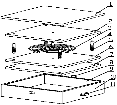
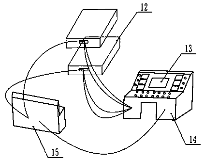
[0026] Such as Figure 1~4 As shown, the embodiment of the present invention provides an electromagnetic induction heating device for vulcanization of steel cord conveyor belt joints, including a heating unit 12, a heating control unit and a temperature monitoring unit.

[0027] Specifically, such as figure 1 As shown, the heating unit 12 includes: a shell 10 with an open top, and the shell 10 is sequenti...


PUM


Abstract

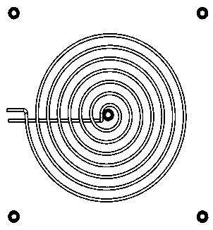
The invention relates to the technical field of underground coal mine steel wire rope core conveying belts, and discloses a steel wire rope core conveying belt connector vulcanization electromagneticinduction heating device. A heating unit, a heating control unit and a temperature monitoring unit are included. The heating unit comprises a shell with the top opened. The shell is internally provided with a lower heat preservation cotton layer, a cushion plate, an upper heat preservation cotton layer and a steel plate from bottom to top in sequence. A disc-shaped electromagnetic coil is arrangedbetween the cushion plate and the upper heat preservation cotton layer. The shell is internally further provided with a plurality of round bars. A columnar electromagnetic coil is arranged on the periphery of each round bar. The bottoms of the round bars are fixedly connected with the cushion plate, the tops penetrate through the upper heat preservation cotton layer and make contact with the steel plate, and a conductive rubber layer is arranged on the inner wall of the shell. The steel plate is used for closing the top opening of the shell. The heating control unit is used for controlling the current input into the disc-shaped electromagnetic coil and the columnar electromagnetic coils, and the temperature measuring unit is used for monitoring and displaying the temperature of the steelplate. The steel wire rope core conveying belt connector vulcanization electromagnetic induction heating device is simple in structure, uniform in heating and capable of being applied to the underground coal mine.

Description

technical field [0001] The invention relates to the technical field of underground steel cord conveyor belts, in particular to a vulcanized electromagnetic induction heating device for joints of steel cord conveyor belts. Background technique [0002] When the vulcanizing machine is vulcanizing, the material needs to be heated. In the prior art, various heating devices for the vulcanizing machine have been developed. For example, the publication number is CN107139363 A. The flat plate heating device includes a heating device, a temperature measuring device, a heating table and an ejecting device. The heating device includes a steam heating device and a heat pipe heating device. The heating device is arranged inside the heating table. Heating resistance, steam box and air pipe. The heat pipe heating device includes electric heating wire, gravity heat pipe and heat transfer oil tank. The surface of the gravity heat pipe is provided with strip-shaped protrusions. Heating is ca...

Claims


Application Information

Patent Timeline
Patent Type & Authority Applications(China)
IPC IPC(8): B29C35/08
CPCB29C35/002B29C35/0805B29C2035/0811
Inventor 李军霞张弘玉李康高峰刘鸣宇
Owner TAIYUAN UNIV OF TECH
Learn More