
Ultra-light steel wire rope linkage type space docking mechanism

A space docking and wire rope technology, which is applied to the docking devices of space navigation vehicles, motor vehicles, space navigation equipment, etc. The effect of reliable separation

Active Publication Date: 2020-07-03
SHANGHAI AEROSPACE SYST ENG INST
View PDF9 Cites 4 Cited by
  • Summary
  • Abstract
  • Description
  • Claims
  • Application Information

AI Technical Summary

Problems solved by technology

[0004] The purpose of this invention is to provide an ultra-light steel wire rope linkage space docking mechanism to solve the problem of the existing space docking mechanism with large structure size, heavy weight and small space. The docking, docking, and lightweight requirements of the aircraft do not match the problem

Method used


Image

  • Ultra-light steel wire rope linkage type space docking mechanism
  • Ultra-light steel wire rope linkage type space docking mechanism
  • Ultra-light steel wire rope linkage type space docking mechanism

Examples


Embodiment 1

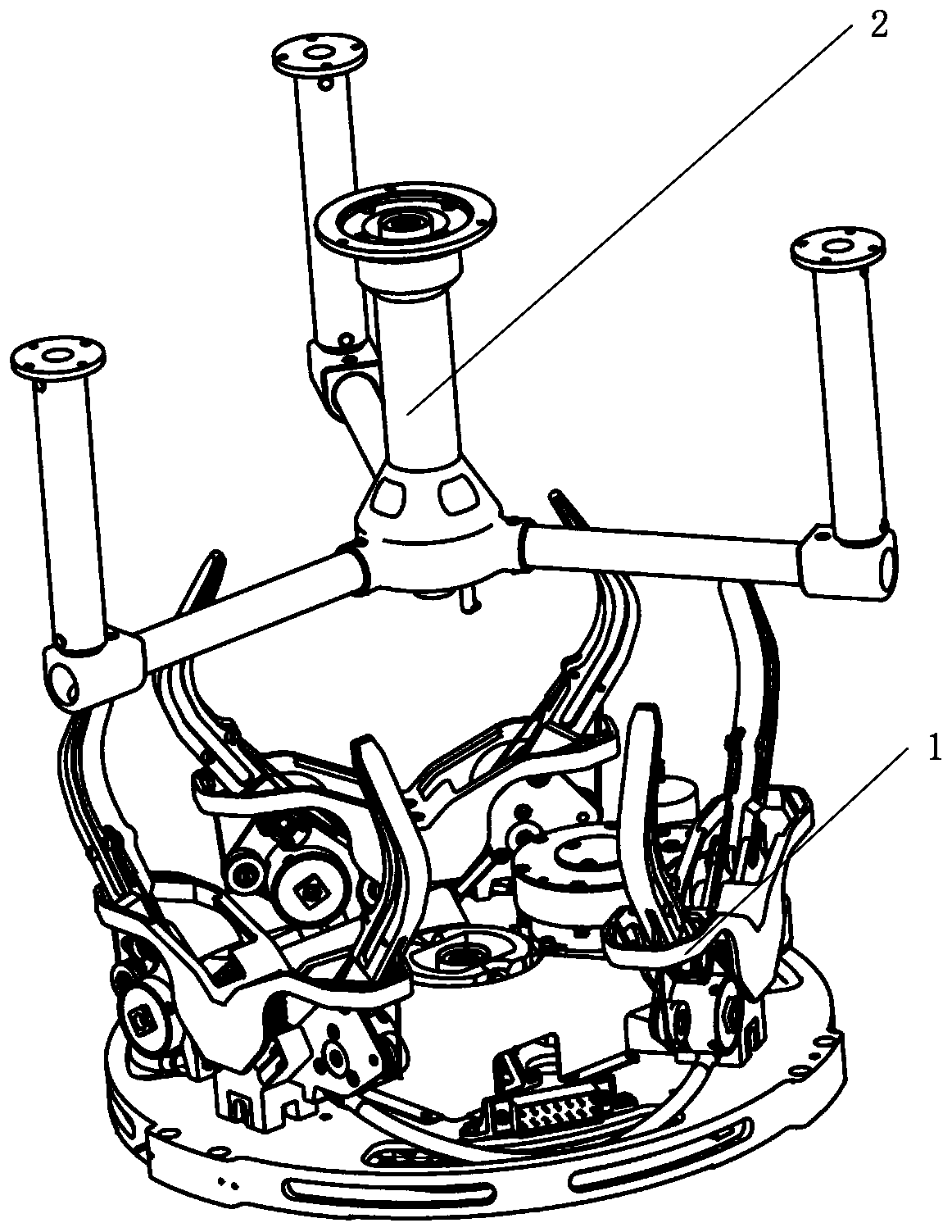
[0022] The invention provides an ultra-light steel wire rope linkage space docking mechanism, such as figure 1 As shown, the space docking mechanism is composed of two parts, the active end 1 and the passive end 2. The active end 1 and the passive end 2 are respectively installed on two independent aircrafts. When docking, each claw of the active end 1 The mechanisms correspond to the positions of the lock handles of the passive end 2 respectively.

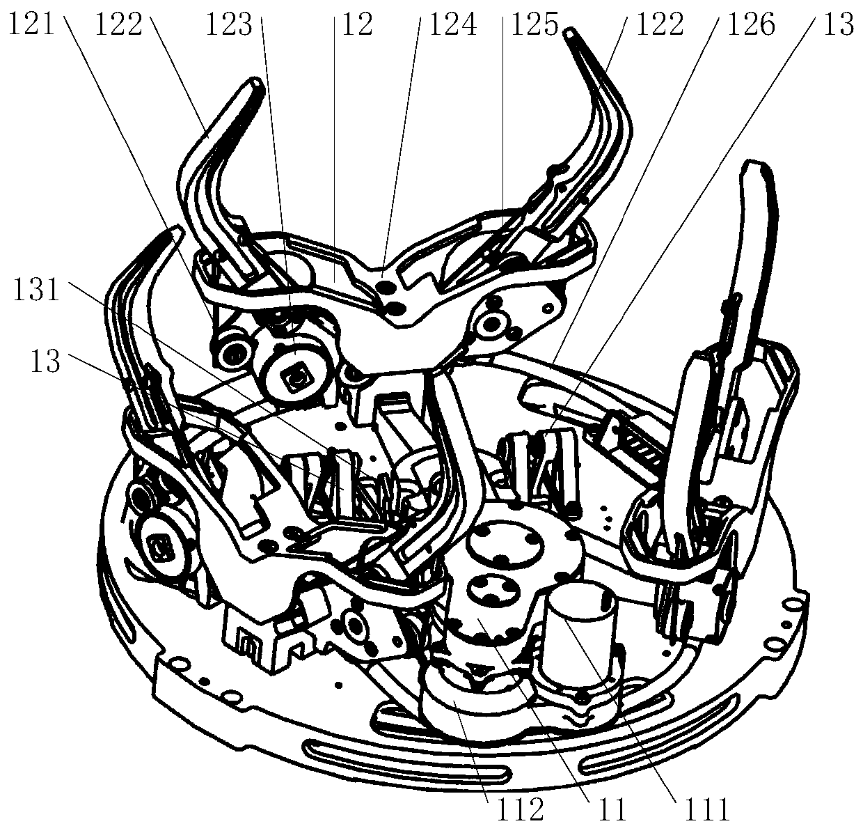
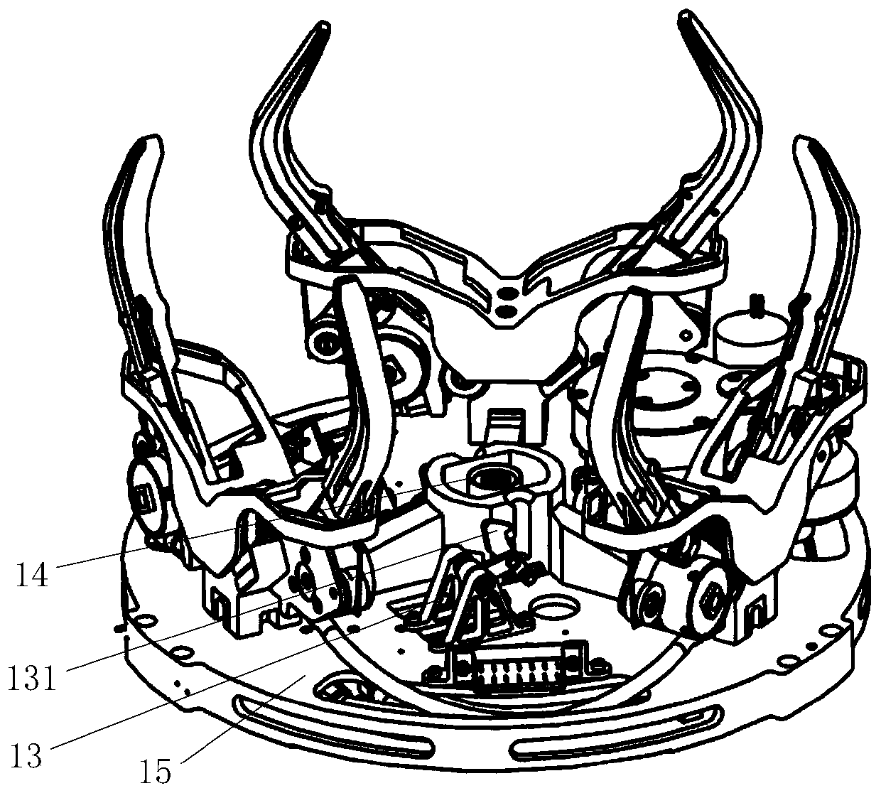
[0023] Such as figure 2 with image 3 As shown, a set of active driving mechanism 11 is installed on one side of the base 15 of the active end 1, three sets of claw mechanisms 12 are uniformly distributed in the circumferential direction, and a set of active end floating electrical connector 14 is installed in the center, and the active end floating electrical connector 14 Two sets of unlocking mechanisms 13 are installed on both sides;

[0024] Such as Figure 4 As shown, a set of slider crank mechanism 16 and four sets of m...

Embodiment 2

[0033] The present invention also provides a docking method of a space docking mechanism, the specific steps are as follows:

[0034] Step 1, capture correction:

[0035] When the active end 1 and the passive end 2 are docked with a certain position deviation, speed and posture, the motor 111 of the active drive mechanism 11 is energized to run, through the gear reducer 112, the crank 162, the connecting rod 163, the slider 164, the lock The tight steel wire rope 125 drives the six lock claws 122 of the three sets of claw mechanisms 12 to retract synchronously. With the retraction of the lock claws 122, the two lock claws 122 of the same set of claw mechanisms 12 form a closed space to complete the active end 1 The capture of the passive end 2; with the further retraction of the locking claw 122, the locking claw 122 collides with the locking handle 202, and finally the locking handle 202 of the passive end 2 is in the position formed by the locking claws 122 and the V-shaped ...


PUM


Abstract

The invention relates to an ultra-light steel wire rope linkage type space docking mechanism. The lightweight advantage of steel wire rope linkage is combined with the characteristic of large tolerance capacity of a claw type docking mechanism, and a design method of the ultra-light space docking mechanism is provided through reasonable structural layout. While the space rendezvous and docking function is achieved, a central channel is reserved, and transmission of electric signals or other information or media is achieved. The problem that an existing space docking mechanism is large in weight inertia is solved.

Description

technical field [0001] The invention relates to a space docking mechanism, in particular to an ultra-light steel wire rope linkage type space docking mechanism. Background technique [0002] In the process of space exploration, the space docking mechanism is widely used in the docking, docking, energy supply, etc. of two aircrafts, and is a necessary device for space exploration. Common space docking mechanism configurations mainly include: peripheral docking mechanism, cone-rod docking mechanism, claw-claw docking mechanism, etc. [0003] The size and weight of the general docking mechanism are relatively large, which cannot meet the docking and docking requirements of micro-aircraft. Therefore, the miniaturization and lightweight design of the docking mechanism is an urgent problem in this field. The present invention aims to utilize the advantages of light weight and convenient layout of steel wire rope transmission to provide an ultra-light steel wire rope linkage space...

Claims


Application Information

Patent Timeline
IPC IPC(8): B64G1/64
CPCB64G1/646
Inventor 肖余之曹燕燕王卫军刘仲刘洲韩大为黄树勇
Owner SHANGHAI AEROSPACE SYST ENG INST
Learn More