
Method and device for testing slurry droplets of wet desulphurization system

A wet desulfurization and slurry technology, applied in measuring devices, sampling devices, weighing by removing certain components, etc., can solve the problems of difficult to clean droplet scale, incomplete recovery of magnesium ions, difficult practical operation, etc. The effect of ensuring accuracy

Pending Publication Date: 2020-07-03
GUODIAN ENVIRONMENTAL PROTECTION RES INST CO LTD +1
View PDF10 Cites 0 Cited by
  • Summary
  • Abstract
  • Description
  • Claims
  • Application Information

AI Technical Summary

Problems solved by technology

[0009] Fourth, at some test points, the sampling gun must be placed vertically
But in fact, since the diameter of the four-turn serpentine glass tube of the second-stage droplet catcher is only 6mm, it is difficult to clean the collected droplet scale after long-term drying, and the recovery of magnesium ions is not complete. The practical difficulties caused by this need to be improved

Method used


Image

  • Method and device for testing slurry droplets of wet desulphurization system
  • Method and device for testing slurry droplets of wet desulphurization system
  • Method and device for testing slurry droplets of wet desulphurization system

Examples


Embodiment 1

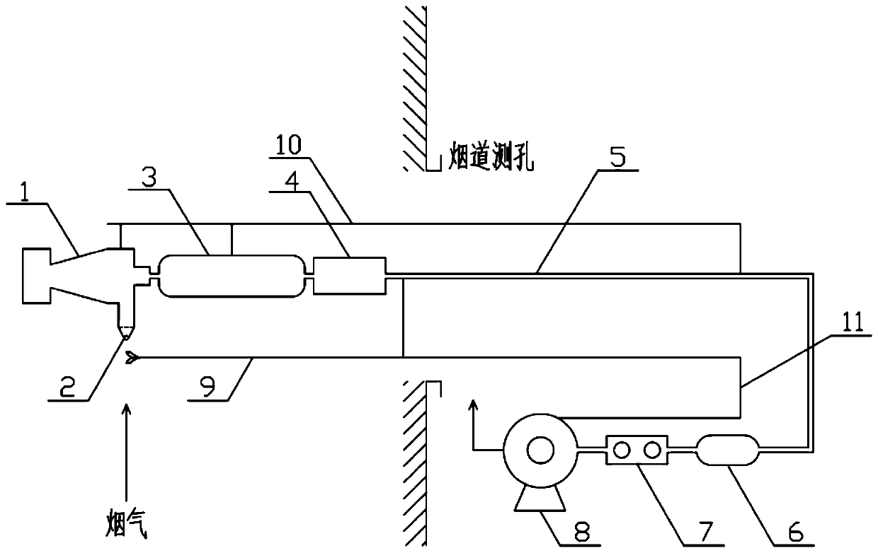
[0058] Such as figure 1 As shown, the slurry mist sampling device of the wet desulfurization system of the present invention comprises in turn: a fog collecting device, a dehumidification device 6, a metering device 7 and a power device 8, and the fog collecting device consists of a cyclone catcher 1, a serpentine tube 3 and The anti-backflow device 4 is formed by connecting, and the mist collecting device is connected with the dehumidification device 6 through the sampling pipe or sampling gun 5 . A sampling nozzle 2 is installed on the intake pipe of the cyclone collector 1; the cyclone collector 1, the serpentine pipe 3, and the anti-backflow device 4 are fixedly connected with the sampling pipe or the sampling gun 5 through the support structure;

[0059] The device also includes an S-shaped pitot tube 9, which is connected to the power unit 8 through a dynamic and static pressure balance communication pipe 11, and the air inlet of the pitot tube is on the same longitudina...

Embodiment 2

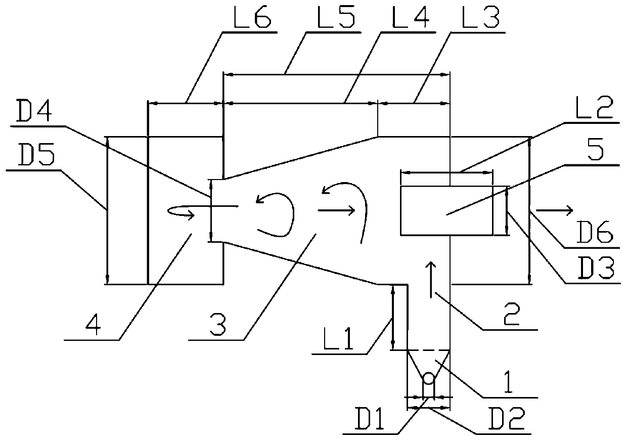
[0062] The optional design of this example is that the structure of the cyclone catcher is as follows figure 2 As shown, the cyclone catcher includes a cone 3, the bottom end of the cone 3 is provided with an air intake pipe 2 for collecting flue gas, the front end of the cone 3 is provided with a mist collection chamber 4 for cutting slurry droplets, and the rear end of the cone 3 is provided with Exit pipe 5 is arranged, links to each other with serpentine pipe. A sampling nozzle 1 is also installed on the intake pipe 2 .

[0063] The extracted flue gas enters the cyclone collector tangentially through the sampling nozzle 1 and the air inlet pipe 2, and the droplets with an aerodynamic diameter of 10 μm or more will be collected in the cone due to centrifugal force and flow into the mist collection chamber; the aerodynamic diameter Droplets below 10 μm follow the airflow, change the direction of the airflow at the entrance of the mist collection chamber, and flow out throu...

Embodiment 3

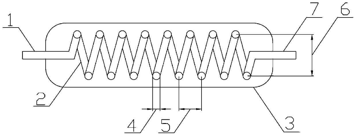
[0065] The optional design of this example lies in, such as figure 1 , The cyclone collector 1, the serpentine pipe 3, and the backflow prevention device 4 are connected through a Teflon connecting pipe; the dehumidification device 6 is filled with hygroscopic silica gel. The metering device 7 is provided with a temperature probe and a pressure probe.


PUM

PropertyMeasurementUnit
diameteraaaaaaaaaa
heightaaaaaaaaaa
particle diameteraaaaaaaaaa

Abstract

The invention relates to a wet desulphurization slurry droplet testing method and device. The method is characterized in that solid content data of slurry droplets carried by the flue gas at an inletflue of a demister is tested, and the mass concentration of the liquid droplets carried by the flue gas at the actual measurement position is corrected, so accuracy of testing the mass concentration of the slurry droplets is improved. The testing device adopts a two-stage combined trapping design of a cyclone trapper and a condenser pipe, has higher overload capacity, and can meet the requirementof testing under the condition of higher droplet concentration, moreover, the liquid drops are collected in a particle size grading manner, so the grading evaluation requirement on the slurry dropletremoval effect of the demister can be met. The method is advantaged in that the solid content of the slurry droplets carried by flue gas on the inlet flue of the demister is tested, therefore, the droplet concentration at other test positions can be corrected, and defects that sources of slurry fog drops carried by the flue gas in a part of single-tower double-circulation wet desulphurization systems are different, quantitative distinguishing cannot be carried out, and liquid drop test data cannot be corrected are overcome.

Description

technical field [0001] The invention belongs to the field of flue gas testing of fixed sources, and in particular relates to a method and device for testing slurry droplets of a wet desulfurization system. It is suitable for wet desulfurization systems, especially after ultra-low emissions, after demister transformation, single-tower double-cycle desulfurization systems, ammonia desulfurization systems, and detection of the mass concentration of slurry droplets in the flue gas of seawater desulfurization systems. Background technique [0002] At present, wet desulfurization technology is the most widely used desulfurization technology, which can meet the requirements of different SO 2 Emission standard requirements, and economically feasible, reliable operation. [0003] In recent years, in order to strengthen the control of air pollution, ultra-low emission transformation has been carried out in the coal power and iron and steel industries. Among them, the modification an...

Claims


Application Information

Patent Timeline
Patent Type & Authority Applications(China)
IPC IPC(8): G01N1/22G01N5/04G01N15/02
CPCG01N1/2211G01N1/2258G01N5/04G01N15/0205G01N2001/2217
Inventor 李军状朱法华段玖祥滕农王新培魏晗孙雪丽吴寒珺
Owner GUODIAN ENVIRONMENTAL PROTECTION RES INST CO LTD
Learn More