Storage battery plate group processing production line

A storage battery and production line technology, applied in the direction of lead-acid battery, lead-acid battery construction, sustainable manufacturing/processing, etc., can solve problems such as low work efficiency, poor automation, and inability to realize automatic input and output of batteries, and achieve the degree of automation High, stable effect

Inactive Publication Date: 2020-07-03
长兴水木机电有限公司
View PDF0 Cites 0 Cited by
  • Summary
  • Abstract
  • Description
  • Claims
  • Application Information

AI Technical Summary

Problems solved by technology

[0005] The purpose of the present invention is to address the shortcomings of the prior art, by setting the pole group on the pole group clamping mechanism to complete the half-entry work with the battery case on the shell clamping mechanism under the drive of the third guide assembly, Then use the casting welding machine to perform casting and welding work on the battery case that is half in the tank, and automatically output after the casting and welding is completed, and then realize the automatic output and input of the battery case during the casting and welding work, thus solving the problem that the device cannot realize The automatic input and output of the storage battery has a poor degree of automation, and it cannot be integrated with the casting and welding work, which is a technical problem of low work efficiency.

Method used


Image

  • Storage battery plate group processing production line
  • Storage battery plate group processing production line
  • Storage battery plate group processing production line

Examples


Embodiment 1

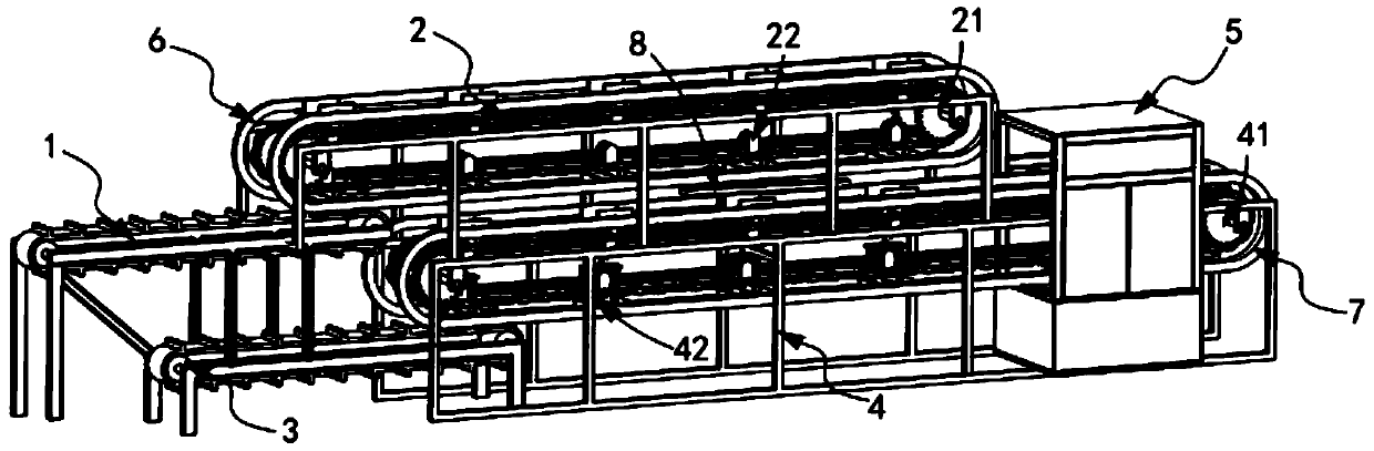
[0052] Such as figure 1 , figure 2 with image 3 As shown, a battery pole group processing production line includes:

[0053] The pole group transmission mechanism 1, the pole group transmission mechanism 1 is used to sequentially transport several groups of pole groups 10 backward;

[0054] The pole group clamping mechanism 2, the pole group clamping mechanism 2 is located above the pole group transmission mechanism 1, and it includes a first transmission assembly 21 and a number of equidistant along the transmission direction of the first transmission assembly 21. A first tightening component 22 assembled and installed on the first conveying component 21;

[0055] A shell transmission mechanism 3, which is located below the pole group clamping mechanism 2, and is used to sequentially transport several groups of battery shells 20 backwards;

[0056] The shell clamping mechanism 4, the shell clamping mechanism 4 is located above the shell transmission mechanism 3, it incl...

Embodiment 2

[0082] Such as Figure 7-Figure 10 As shown, the components that are the same as or corresponding to those in the first embodiment are marked with the corresponding reference numerals in the first embodiment. For the sake of simplicity, only the differences from the first embodiment will be described below. The difference between this embodiment two and embodiment one is:

[0083] further, such as Figure 7-Figure 10As shown, the first guide assembly 6 includes two sets of guide rails a61 installed on the machine tool 211, and the distance between the two sets of guide rails a61 forms a clamping portion a62 and a limiting portion a63. The distance of the holding portion a62 from the input end to the output end decreases gradually, and the distance of the limiting portion a63 from the input end to the output end remains constant.

[0084] In this embodiment, by setting the control member 227 to cooperate with the guidance of the guide track a61, the two sets of splints 2263 a...


PUM


Abstract

The invention relates to a storage battery pole group processing production line, which comprises a pole group transmission mechanism, a pole group clamping mechanism; a housing transmission mechanism; a housing clamping mechanism; and a cast-weld machine; the first guiding assembly controls the first hooping assembly to clamp the pole group in a conveying state and convey the pole group backwards; the second guiding assembly controls the second hooping assembly to clamp the storage battery shell in the conveying state and convey the storage battery shell backwards. The third guiding assemblypushes down the plate group clamped on the first hooping assembly and inserts the plate group into the storage battery shell clamped by the correspondingly arranged second hooping assembly; accordingto the invention, the technical problems are solved that the device cannot realize automatic input and output of the storage battery, is poor in automation degree, cannot be integrally connected withcast-weld work for work, and is low in working efficiency.

Description

technical field [0001] The invention relates to the technical field of battery pole groups, in particular to a battery pole group processing production line. Background technique [0002] Lead storage battery is a reversible DC power supply, which can convert chemical energy into electrical energy, and at the same time convert electrical energy into chemical energy. Lead storage battery is mainly composed of electrolyte, battery tank and pole group. The electrolyte of lead storage battery is sulfuric acid solution. The pole group is mainly composed of a positive plate, a negative plate and a separator. The separator is mainly used to store the electrolyte and serve as a gas channel for oxygen recombination to prevent the active material from falling off and the short circuit between the positive and negative electrodes. The positive and negative plates Consists of grids and active substances. [0003] The patent document with the patent number CN2018216513970 discloses a de...

Claims


Application Information

Patent Timeline
Patent Type & Authority Applications(China)
IPC IPC(8): H01M10/14B65G17/12B65G17/34B65G17/46B65G47/90
CPCB65G17/123B65G17/34B65G17/46B65G47/90H01M10/14Y02E60/10Y02P70/50
Inventor 周杰庄阳
Owner 长兴水木机电有限公司
Why Eureka
Try Eureka