Manufacturing method of permanent magnet motor rotor

A technology for permanent magnet motors and manufacturing methods, which is applied in the manufacture of motor generators, stator/rotor bodies, electromechanical devices, etc., and can solve the problem that epoxy potting adhesives cannot meet the requirements of high temperature resistance, mass production of motors, Affect the reliability of the motor rotor and other issues to achieve the effect of avoiding air bubbles and holes, improving potting efficiency, and reducing the possibility

Active Publication Date: 2020-07-03
襄阳中车电机技术有限公司 +1
View PDF8 Cites 0 Cited by
  • Summary
  • Abstract
  • Description
  • Claims
  • Application Information

AI Technical Summary

Problems solved by technology

[0010] This process uses epoxy potting glue to fill the gap between the rotor permanent magnet and the iron core. This traditional method of impregnating epoxy impregnating paint is complicated and cannot meet the requirements of mass manufacturing of motors. In the special application environment of rail transit permanent magnet motors, epoxy potting adhesives cannot meet the high temperature resistance requirements above 200°C, and the shock resistance after potting and curing is not good, and it is easily affected by vibration and shock, resulting in failure of the filling part; at the same time, the traditional potting The core part of the sealing process is prone to loss of potting glue, resulting in air bubbles or cavities in the filling part, which affects the reliability of the motor rotor

Method used


Image

  • Manufacturing method of permanent magnet motor rotor
  • Manufacturing method of permanent magnet motor rotor
  • Manufacturing method of permanent magnet motor rotor

Examples


preparation example Construction

[0047] In the step (3), in the process of potting, the potting glue 15 used is an addition-type silicone rubber; the preparation method of the potting glue 15 comprises: adding a two-component main agent of the addition-type silicone rubber and The accelerator is mixed, stirred evenly, and degassed for 10-15 minutes under the condition that the vacuum degree is not higher than 100Pa, and the product is obtained. The two-component main agent and accelerator of the addition type silicone rubber are common in the field.

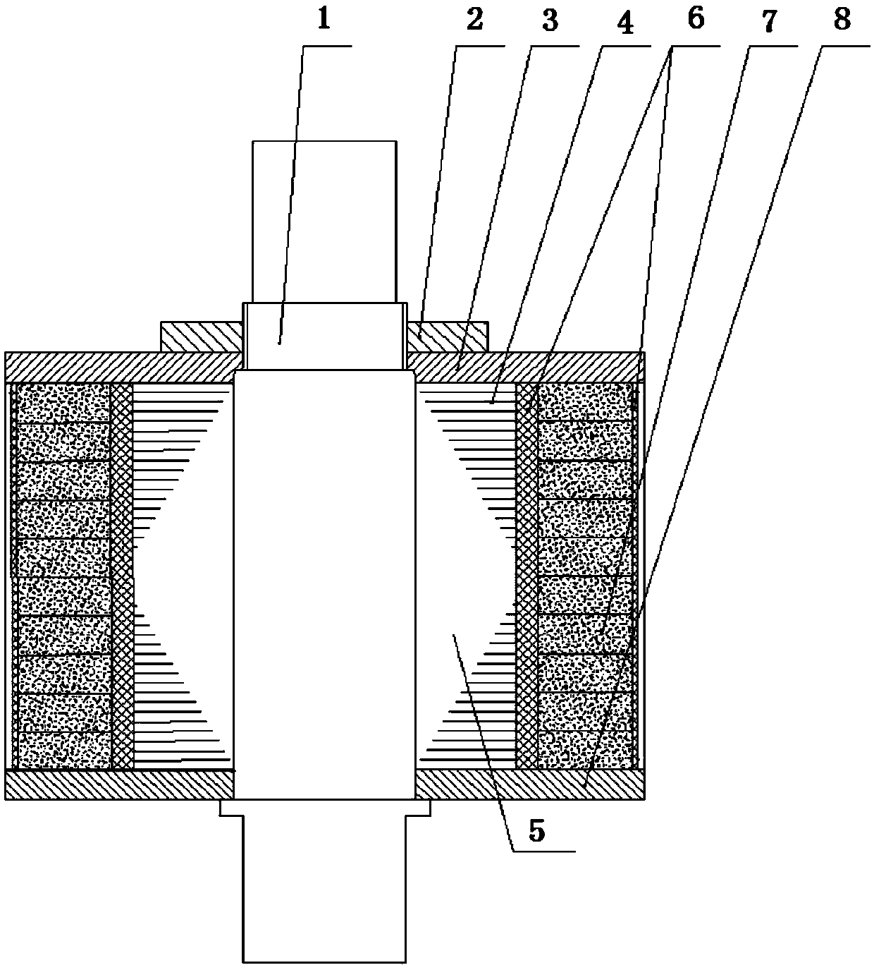
[0048] In the step (3), the potting includes: stirring the mixed potting compound 15 evenly, degassing under vacuum conditions, and then injecting into the gap between the permanent magnet 7 and the rotor punch 4 .

[0049] Before the potting glue 15 is injected into the gap between the permanent magnet 7 and the rotor punch 4, it also includes preheating the semi-finished product; the preheating condition is to preheat at 100-110° C. for 1-1.5 hours.

[0050] W...

Embodiment 1

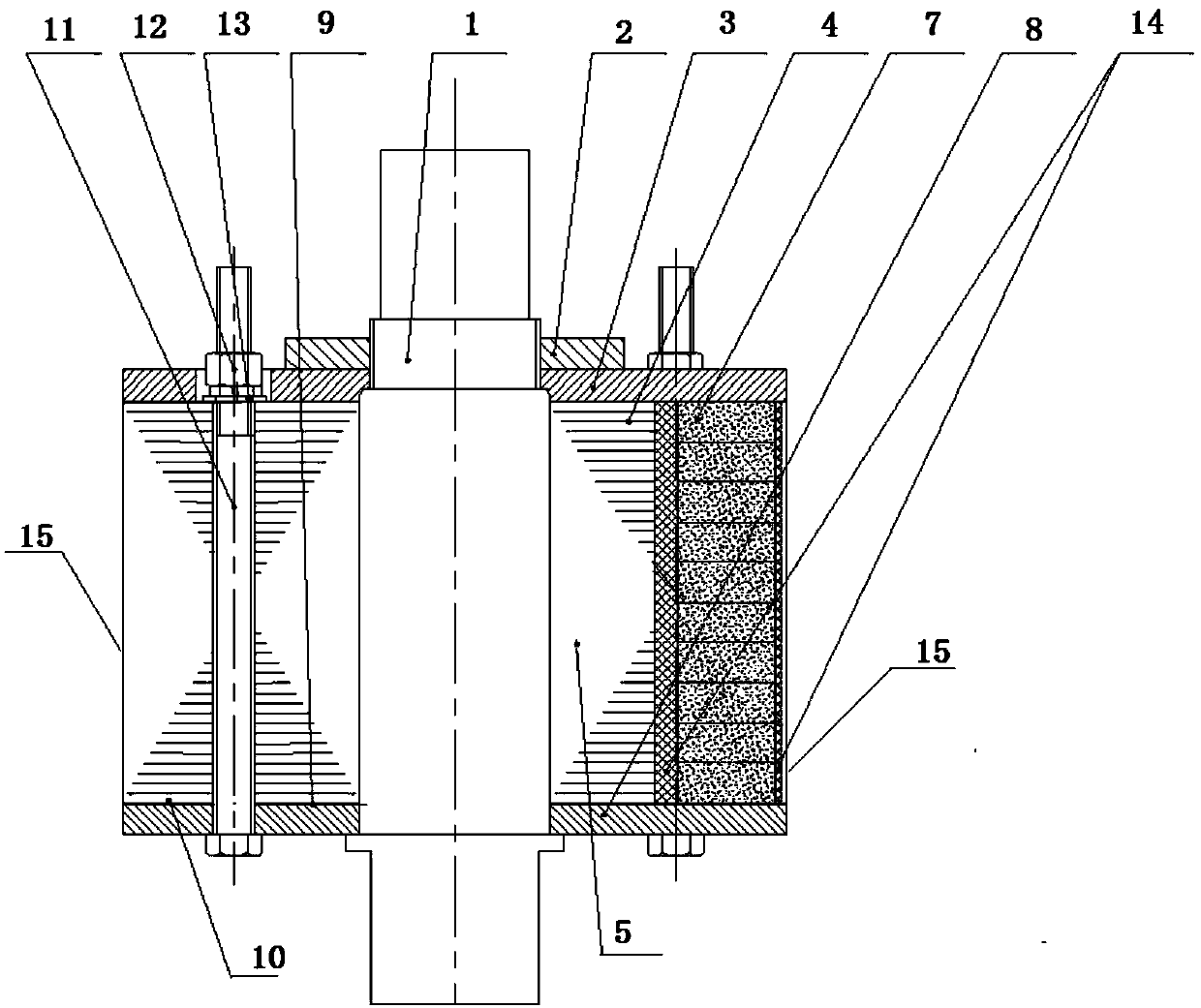
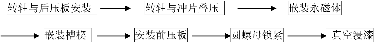
[0053] A manufacturing method of the permanent magnet motor rotor of the present invention, the assembly schematic diagram of the permanent magnet motor rotor is as follows figure 2 As shown, the process flow is as follows:

[0054]

[0055] Concrete manufacturing method comprises the steps:

[0056] (1) cutting the polyimide film 9 according to the size of the first pressing plate 8, leaving holes corresponding to the installation holes of the first pressing plate 8 on the polyimide film 9 obtained by cutting; Both sides of the imide film 9 are coated with the first high-temperature-resistant silicone grease layer 10, the coating thickness is 0.1-0.2mm, and then the polyimide film 9 is pasted on the surface of the first pressure plate 8, and the surface of the polyimide film 9 is The reserved installation holes are aligned with the installation holes of the first pressure plate 8, so that they form a whole and constitute the first assembly.

[0057] (2) After inserting ...

Embodiment 2

[0064] A method for manufacturing a permanent magnet motor rotor of the present invention, the steps are basically the same as the steps in Example 1, and the differences are as follows:

[0065] The structure of the first assembly in step (1) is different. The step (1) of this embodiment is to coat a Teflon coating on one surface (ie, the upper surface) of the first pressing plate 8 to form the first assembly, that is, the present embodiment Example A Teflon coating is used to replace the polyimide film 9 whose surface is coated with the first high-temperature-resistant silicone grease layer 10 in Example 1, and the thickness of the Teflon coating is 20-30 μm.

[0066] In step (2), in this embodiment, the second high-temperature-resistant silicone grease layer 14 is replaced by brushing Teflon coating on the peripheral surface of the rotor core, and the Teflon coating thickness is 20-30 μm.

[0067] In step (1), the polyimide film 9 of the first high-temperature-resistant sil...


PUM

PropertyMeasurementUnit
thicknessaaaaaaaaaa
thicknessaaaaaaaaaa
thermal conductivityaaaaaaaaaa

Abstract

The invention discloses a manufacturing method for a permanent magnet motor rotor. The method comprises the steps: coating a first surface of a polyimide film with a first high-temperature-resistant silicone grease layer, and adhering the second surface of the polyimide film on the surface of a first pressing plate to form a first assembly, or directly coating the surface of the first pressing plate with a Teflon coating to form the first assembly; sequentially sleeving the first assembly and a rotor punching sheet on a rotating shaft, then tightly pressing the first assembly and the rotor punching sheet to enable the rotor punching sheet to be laminated to form a rotor core, and then locking the rotor core and the first assembly; assembling a permanent magnet in the rotor core to obtain asemi-finished product, pouring a glue into the gap between the permanent magnet and the rotor punching sheet, and curing the pouring glue to obtain a workpiece; and installing a second pressing plateon the obtained workpiece, and locking the workpiece and the second pressing plate to obtain the permanent magnet motor rotor. The method is simple in technological process, easy to implement and lowin cost, and pouring sealant loss can be effectively prevented while high reliability of the rotor is guaranteed.

Description

technical field [0001] The invention relates to the field of motor rotors, in particular to a method for manufacturing a permanent magnet motor rotor. Background technique [0002] The existing rail transit permanent magnet motor rotor usually consists of a rotor core 5 composed of a rotating shaft 1 and a rotor punch 4, a permanent magnet 7, a front pressure plate 3, a rear pressure plate 8, a round nut 2, and a rotor wedge 6, such as figure 1 shown. [0003] Theoretically, the smaller the gap between the rotor permanent magnet and the rotor core and the rotor slot wedge, the better the fastening effect, but in fact, there is a certain dimensional tolerance in the permanent magnet itself, and there must be a certain process gap in the permanent magnet assembly. To ensure its installation efficiency, the gap between the permanent magnet of the permanent magnet rotor and the iron core and the slot wedge cannot be avoided. The actual gap between the permanent magnet and the i...

Claims


Application Information

Patent Timeline
Patent Type & Authority Applications(China)
IPC IPC(8): H02K15/03
CPCH02K15/03H02K2213/03
Inventor 谭林王新剑黄谷香雷军黄德聪尹琨罗祥程包华羽殷茜
Owner 襄阳中车电机技术有限公司
Why Eureka
Try Eureka