A low temperature plasma device and method of decomposing hydrogen sulfide

A low-temperature plasma and hydrogen sulfide technology, applied in the field of plasma chemistry, can solve the problems of low conversion rate of hydrogen sulfide and high energy consumption for decomposition

Pending Publication Date: 2020-07-07
CHINA PETROLEUM & CHEM CORP +1
View PDF9 Cites 0 Cited by
  • Summary
  • Abstract
  • Description
  • Claims
  • Application Information

AI Technical Summary

Problems solved by technology

[0009] The purpose of the present invention is to overcome the defects of low hydrogen sulfide conversion rate and high decomposition energy consumption in the low-temperature plasma reaction device provided by the prior art when it is used for the decomposition of hydrogen sulfide, and provide a new method that can improve the conversion rate of hydrogen sulfide And a low-temperature plasma reaction device for reducing decomposition energy consumption and a method for decomposing hydrogen sulfide using the reaction device

Method used


Image

  • A low temperature plasma device and method of decomposing hydrogen sulfide

Examples


Embodiment 1

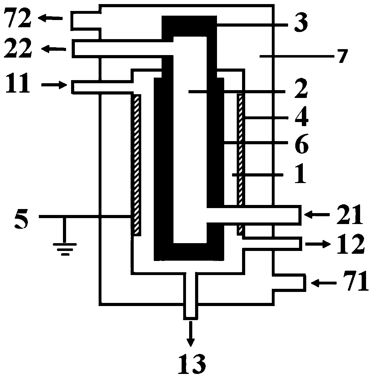
[0113] use figure 1 The plasma reaction device shown performs hydrogen sulfide decomposition reaction. The specific structure and structural parameters of the plasma reaction device are as follows:

[0114] The reaction device includes:

[0115] A first cavity, the first cavity is respectively provided with a first inlet, a gas product outlet, and a liquid product outlet;

[0116] A second cavity, the second cavity is nested inside the first cavity, and a second inlet and a second outlet are respectively provided on the second cavity; the side walls of the second cavity are both It is formed by internal electrodes, the material for forming the internal electrodes is stainless steel, and the internal electrodes are connected to a high-voltage power supply;

[0117] A third cavity, the third cavity is nested outside the first cavity, and a third inlet and a third outlet are respectively provided on the third cavity; forming the third cavity Material is stainless steel;

[0118] The out...

Embodiment 2

[0145] In this embodiment, a plasma reaction device similar to that in embodiment 1 is used to carry out the decomposition reaction of hydrogen sulfide. The difference is that in this embodiment:

[0146] All side walls of the first cavity are formed by external electrodes, the material for forming the external electrodes is stainless steel metal foil, the external electrodes are connected to a high-voltage power supply, and the internal electrodes are grounded;

[0147] L 2 And the thickness of the blocking medium D 1 The ratio of is 15:1; and H 1 : L 3 =1:120.

[0148] In this embodiment, H is introduced into the first cavity of the plasma reaction device from the first inlet 2 S / H 2 Mixed gas, where H 2 The volume fraction of S is 80%, the flow rate of the mixed gas is controlled so that the average residence time of the gas in the discharge zone is 18.7s, and the reaction pressure in the first cavity of the reactor is maintained at 0.04 MPa in this embodiment. H 2 S / H 2 After the...

Embodiment 3

[0152] In this embodiment, a plasma reaction device similar to that in embodiment 1 is used to carry out the decomposition reaction of hydrogen sulfide. The difference is that in this embodiment:

[0153] The outer electrode is arranged on the inner side wall of the first cavity, the material for forming the outer electrode is copper foil, the outer electrode is grounded, and the inner electrode is connected to a high-voltage power supply;

[0154] The barrier medium is arranged on the outer surface of the part where the inner electrode extends into the first cavity, and the upper edge of the barrier medium is higher than the upper edge of the solid ground electrode. The material of the barrier medium is ceramic ;

[0155] L 2 And the thickness of the blocking medium D 1 The ratio is 0.7:1; and H 1 : L 2 =1:250.

[0156] In this embodiment, H is introduced into the first cavity of the plasma reaction device from the first inlet 2 S / Ar mixture, where H 2 The volume fraction of S is 25%...


PUM


Abstract

The invention relates to the field of plasma chemistry, and discloses a low-temperature plasma device and a method for decomposing hydrogen sulfide; the device comprises a first cavity (1), a second cavity (2), a third cavity (7), an inner electrode (3), an outer electrode (4) and a blocking medium (6), wherein the inner electrode (3) and the outer electrode (4) are both solid electrodes, and theshapes of the inner electrode (3) and the outer electrode (4) are mutually matched to form an equal-diameter structure. According to the low-temperature plasma reaction device provided by the invention, the hydrogen sulfide decomposition process can be continuously and stably carried out under the condition of obviously higher hydrogen sulfide conversion rate, and the device can realize long-period operation.

Description

Technical field [0001] The invention relates to the field of plasma chemistry, in particular to a low-temperature plasma device and a method for decomposing hydrogen sulfide. Background technique [0002] Hydrogen sulfide (H 2 S) is a highly toxic and foul-smelling acidic gas, which not only causes corrosion of metals and other materials, but also harms human health and pollutes the environment. At present, the large and medium-sized oil refineries in my country adopt the traditional Claus method (Claus) to treat H-containing 2 S tail gas, and recover sulfur. This method only recovers the sulfur in hydrogen sulfide, but converts precious hydrogen into water. From the perspective of comprehensive utilization of resources, in the traditional hydrogen sulfide recovery process, hydrogen resources have not been effectively used. [0003] Therefore, the decomposition of hydrogen sulfide into sulfur and hydrogen has gradually become a technical field that domestic and foreign researcher...

Claims


Application Information

Patent Timeline
IPC IPC(8): C01B17/04C01B3/04
CPCC01B3/04C01B17/0495Y02E60/36
Inventor 张铁张婧任君朋石宁徐伟孙峰朱云峰李亚辉周明川
Owner CHINA PETROLEUM & CHEM CORP
Why Eureka
Try Eureka