Plasma reactor and method for decomposing hydrogen sulfide

A plasma and reactor technology, applied in the field of plasma chemistry, can solve the problems of high energy consumption for decomposition and low conversion rate of hydrogen sulfide, and achieve the effect of flexible temperature control and long-term operation

Pending Publication Date: 2019-08-16
CHINA PETROLEUM & CHEM CORP +1
View PDF5 Cites 0 Cited by
  • Summary
  • Abstract
  • Description
  • Claims
  • Application Information

AI Technical Summary

Problems solved by technology

[0015] The purpose of the present invention is to overcome the defects of low hydrogen sulfide conversion rate and high decomposition energy consumption in the plasma reactor provided by the prior art when it is used for the decomposition of hydrogen sulfide, and to provide a new method that can improve the hydrogen sulfide conversion rate and Plasma reactor for reducing decomposition energy consumption and method for decomposing hydrogen sulfide using the reactor

Method used


Image

  • Plasma reactor and method for decomposing hydrogen sulfide

Examples


specific Embodiment approach

[0083] Nitrogen gas is introduced into the inner cylinder of the plasma reactor from the reactor inlet to remove the air in the discharge area, and the gas is drawn out from the product outlet. At the same time, the heat transfer medium is introduced into the outer cylinder from the heat transfer medium inlet, and the introduced heat transfer medium is led out from the heat transfer medium outlet. The temperature of the heat transfer medium is maintained at the temperature required by the system reaction. Then feed the raw material gas containing hydrogen sulfide into the inner cylinder of the plasma reactor from the reactor inlet, and turn on the high-voltage power supply after the raw material gas flow is stable, and form a plasma discharge field between the center electrode and the ground electrode by adjusting the voltage and frequency . The hydrogen sulfide gas is ionized in the discharge area and decomposed into hydrogen and elemental sulfur. The elemental sulfur produc...

Embodiment 1

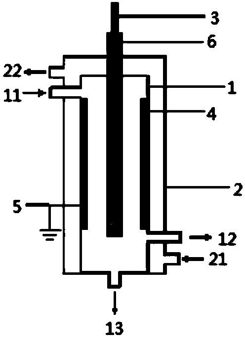
[0094] use figure 1 The shown plasma reactor carries out hydrogen sulfide decomposition reaction, and the specific structure and structural parameters of the plasma reactor are as follows:

[0095] The reactor includes:

[0096] an inner cylinder, the inner cylinder is respectively provided with a reactor inlet, a gas product outlet and a liquid product outlet;

[0097] An outer cylinder, the outer cylinder is nested outside the inner cylinder, and the outer cylinder is respectively provided with a heat transfer medium inlet and a heat transfer medium outlet;

[0098] A central electrode, the central electrode is arranged at the central axis of the inner cylinder, and the material forming the central electrode is a stainless steel metal rod;

[0099] A ground electrode, the ground electrode is arranged on the inner side wall of the inner cylinder, the material forming the ground electrode is stainless steel metal foil, and the lower edge of the center electrode in this embod...

Embodiment 2

[0127] The present embodiment adopts the plasma reactor similar to embodiment 1 to carry out the decomposition reaction of hydrogen sulfide, the difference is, in the present embodiment:

[0128] All side walls of the inner cylinder are formed by grounding electrodes, and the material for forming the grounding electrodes is stainless steel metal foil;

[0129] The distance L between the outer wall of the barrier medium and the inner wall of the ground electrode (that is, the inner wall of the inner cylinder) 1 with the thickness of the barrier dielectric D 1 The ratio is 25:1;

[0130] h 1 and the length L of the discharge region containing the barrier dielectric 2 The proportional relationship between is: H 1 :L 2 =1:120.

[0131] In this embodiment, H is introduced into the inner cylinder of the plasma reactor from the reactor inlet. 2 S / Ar mixed gas, where H 2 The volume fraction of S is 30%, and the flow rate of the mixed gas is controlled so that the average resid...


PUM


Abstract

The invention relates to the field of plasma chemistry, and discloses a plasma reactor and a method for decomposing hydrogen sulfide. The reactor comprises: an inner cylinder (1); an outer cylinder (2) nested in the outer portion of the inner cylinder (1); a center electrode (3) arranged in the inner cylinder (1); a grounding electrode (4) formed by a solid electric-conduction material, wherein the grounding electrode forms at least part of the side wall of the inner cylinder or is arranged around the inner side wall of the inner cylinder; and a barrier medium (6) arranged on at least part ofthe outer surface of the center electrode (3). According to the present invention, the low temperature plasma reactor can achieve the continuous and stable performing of the hydrogen sulfide decomposition process at a significantly high hydrogen sulfide conversion rate, and can achieve long-cycle operation.

Description

technical field [0001] The invention relates to the field of plasma chemistry, in particular to a plasma reactor and a method for decomposing hydrogen sulfide. Background technique [0002] Hydrogen sulfide (H 2 S) is a highly toxic and foul-smelling acid gas, which not only causes corrosion of metals and other materials, but also endangers human health and pollutes the environment. At present, large and medium-sized refineries in my country adopt the traditional Claus method (Claus) to treat 2 S tail gas, and recover sulfur. The method recovers only the sulfur in hydrogen sulfide, but converts the valuable hydrogen into water. From the perspective of comprehensive utilization of resources, hydrogen resources have not been effectively utilized in the traditional hydrogen sulfide recovery process. Therefore, the decomposition of hydrogen sulfide into sulfur and hydrogen has gradually become a technical field that researchers at home and abroad pay close attention to. [...

Claims


Application Information

Patent Timeline
Patent Type & Authority Applications(China)
IPC IPC(8): C01B3/04C01B17/04B01D53/32
CPCB01D53/323B01D2257/304C01B3/04C01B17/0495C01B2203/0277Y02E60/36
Inventor 孙万付张婧张铁任君朋李亚辉石宁朱云峰
Owner CHINA PETROLEUM & CHEM CORP
Why Eureka
Try Eureka