Multifunctional solar cell roof structure

A technology of solar cells and roof structures, which is applied in the directions of solar thermal power generation, solar thermal energy, solar thermal collectors, etc., can solve the problems that it is difficult to meet the cost of convenient disassembly and assembly, reliable quality and high requirements.

Pending Publication Date: 2020-07-07
永康市凡谷进出口有限公司
View PDF0 Cites 0 Cited by
  • Summary
  • Abstract
  • Description
  • Claims
  • Application Information

AI Technical Summary

Problems solved by technology

[0002] There are two structures for the installation of solar cell roofs. First, install solar cells on the existing roof. This structure does not need to consider the impact of solar cell leakage on the existing roof, and is more suitable for the structure of old houses; second, directly integrate solar energy As a part of the roof, the battery needs to have the function of preventing water leakage. This structure can be used as the roof structure of a new house, which can reduce the cost of the house, but the requirements for this structure are relatively high, because the glass used for solar cells is not very thick and the area is relatively large. Large, if encountering weather such as hail, it is relatively easy to break, so it needs to be easily replaced. In the structure of the prior art, it is difficult to meet the conditions of low cost, convenient disassembly and assembly, and reliable quality.

Method used


Image

  • Multifunctional solar cell roof structure
  • Multifunctional solar cell roof structure
  • Multifunctional solar cell roof structure

Examples


Embodiment 1

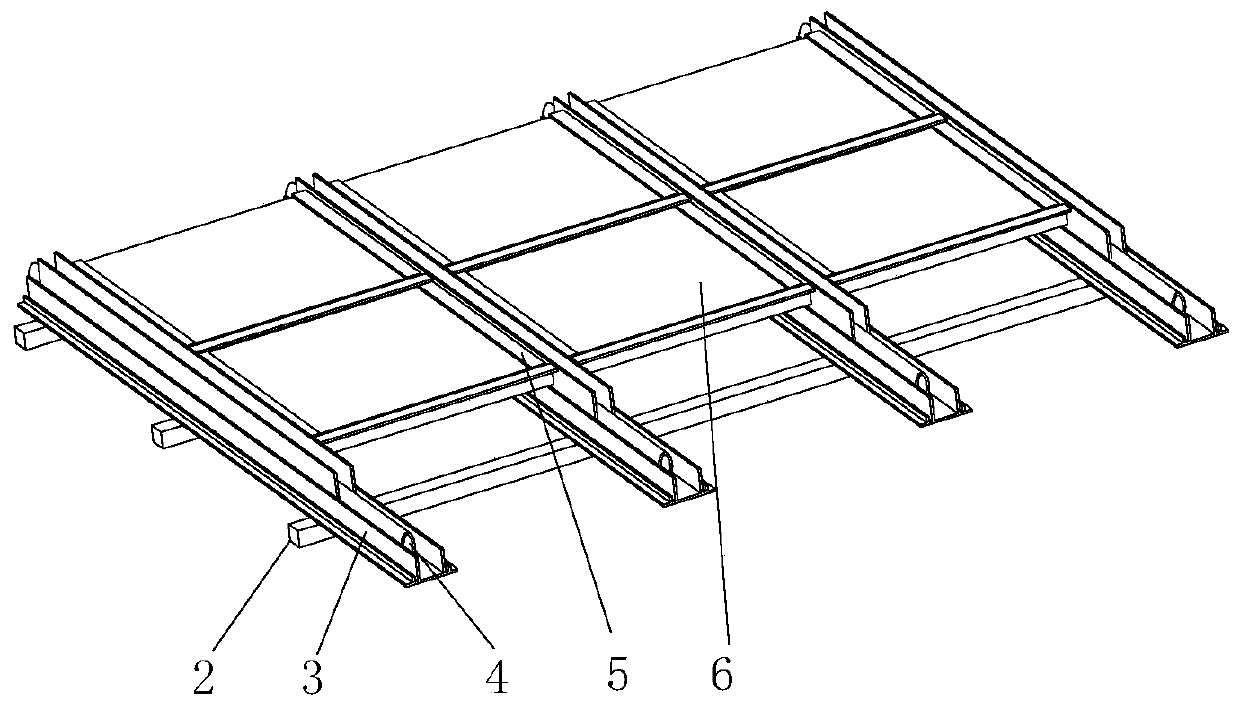
[0029] Example 1, such as figure 1 Shown:

[0030] A multifunctional solar cell roof structure comprising:

[0031] There are multiple longitudinal beams 3, and the multiple longitudinal beams 3 are equidistantly and obliquely fixed to the multiple roof beams 2, and the longitudinal beams 3 are provided with longitudinal grooves 31;

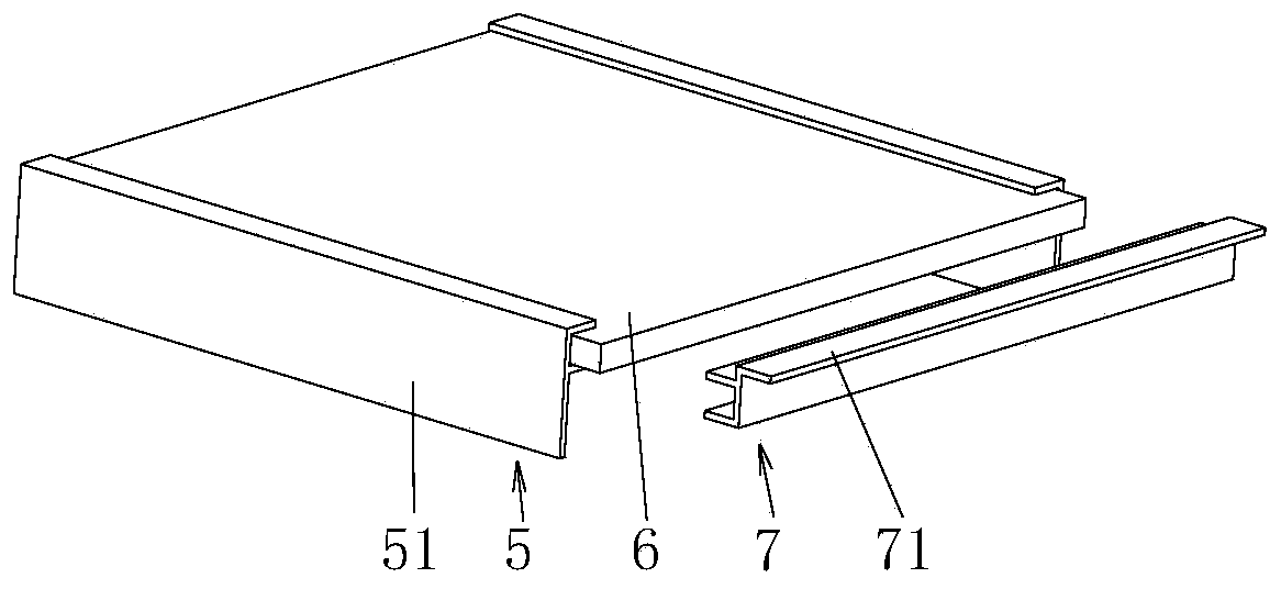
[0032] There are multiple solar cell assemblies, each solar cell assembly is provided with a solar cell 6, symmetrical side frames 5 are respectively installed on both sides of the solar cell 6, the side frame 5 is provided with a side plate 51, and the bottom side of the solar cell 6 A base frame 7 is installed, and the base frame 7 is provided with a bottom plate 71, and multiple solar cell assemblies can be installed between two adjacent longitudinal beams 3. Among multiple solar cell assemblies in the same column, the bottom plate 71 of the upper solar cell assembly can Covering the top of the solar cell module below, in the same row of sol...

Embodiment 2

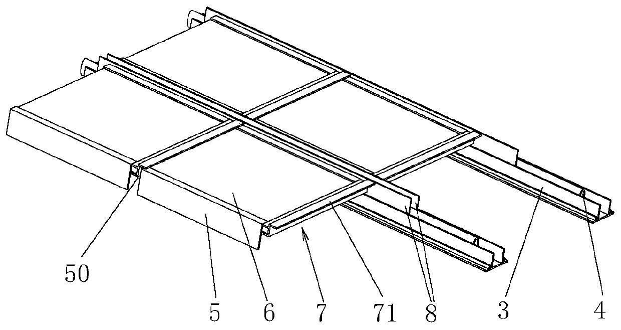
[0036] Example 2, such as figure 2 , 3 and 4 as shown:

[0037] We know that the fixed elastic strip will reduce its elasticity after aging for a long time, thereby affecting the installation firmness of the solar cell module. In order to solve this technical problem, on the basis of embodiment 1, the elastic strip 4 is an elastic tube. The round tube, the elastic tube is filled with liquid and / or gas and can generate pressure, which can further compress the side plate 51 of the solar cell module and the side wall of the longitudinal groove 31 .

[0038] It should be noted that both ends of the elastic tube can be sealed after being pressurized and filled with liquid and / or gas, such as through a bulky head seal, and the elastic tube can be a silicon rubber tube, etc., which is resistant to high temperature and has a long service life.

[0039] In addition, the pressure of the elastic tube can increase the elastic force of the elastic tube, thereby prolonging the service li...

Embodiment 3

[0042] Example 3, such as Figure 5 Shown:

[0043] In order to adjust the pressure conveniently, on the basis of Example 2, the elastic tube is connected with a pressure regulating device. When the solar cell module needs to be disassembled, the pressure can be reduced through the pressure regulating device. Under normal conditions, the pressure regulating device can increase the pressure through the elastic tube. .

[0044] Further, the pressure regulating device includes:

[0045] The first sealing tube 41 communicates with one end of a plurality of elastic tubes through the interface;

[0046] The second sealing tube 45 communicates with the other end of the plurality of elastic tubes through the interface;

[0047] An air bag 44, which communicates with the first sealed tube 41 or the second sealed tube 45 via a pipeline, the air bag 44 is filled with liquid and / or gas, and the air bag 44 is placed on the platform;

[0048] The weight 42 is pressed on the air bag 44 a...


PUM


Abstract

The invention discloses a multifunctional solar cell roof structure, and the structure comprises a longitudinal beam which is provided with longitudinal grooves and is fixed with a plurality of roof cross beams at equal intervals in an inclined manner; a solar cell module which is provided with a solar cell, wherein symmetrical side frames are installed on the two sides of the solar cell respectively. The side frame is provided with a side plate; a bottom frame is installed on the bottom side of the solar cell, a bottom plate is arranged on the bottom frame, a plurality of solar cell assemblies can be installed between every two adjacent longitudinal beams, the bottom plate of the upper solar cell assembly can cover the top of the lower solar cell assembly, and in the solar cell assemblies, the side plates on the same side can be inserted into the longitudinal grooves of the same longitudinal beam. The cover plate can cover a side gap between two adjacent solar cell modules; the elastic strips are inserted into the longitudinal grooves and can compress the cover plate, the side plates and the side walls of the longitudinal grooves, and each solar cell module can be rapidly disassembled and assembled in a pluggable mode. The structure has the advantages of being simple in structure, convenient to disassemble and assemble and capable of generating hot water.

Description

technical field [0001] The invention relates to a multifunctional solar battery roof structure. Background technique [0002] There are two structures for the installation of solar cell roofs. First, install solar cells on the existing roof. This structure does not need to consider the impact of solar cell leakage on the existing roof, and is more suitable for the structure of old houses; second, directly integrate solar energy As a part of the roof, the battery needs to have the function of preventing water leakage. This structure can be used as the roof structure of a new house, which can reduce the cost of the house, but the requirements for this structure are relatively high, because the glass used for solar cells is not very thick and the area is relatively large. Large, if it encounters weather such as hail, it is relatively easy to break, so it needs to be easily replaced. In the structure of the prior art, it is difficult to meet the conditions of low cost, conveni...

Claims


Application Information

Patent Timeline
IPC IPC(8): H02S20/23H02S40/42E04D13/00E04D13/18E04D13/16F24S25/37F24S25/632
CPCE04D13/00E04D13/16F24S25/37F24S25/632H02S20/23H02S40/425Y02B10/10Y02B10/20Y02E10/47Y02E10/50
Inventor 付燕萍
Owner 永康市凡谷进出口有限公司
Why Eureka
Try Eureka