Oil filtering device and integrated cooker with oil filtering device

An oil filter device and integrated stove technology, which is applied in the field of integrated stoves, can solve the problems of inability to filter oil, doping with grease, and the effect of hood in absorbing oil fume is reduced, so as to facilitate disassembly and assembly, reduce emissions, and avoid the effects of falling effect

Pending Publication Date: 2020-07-10
QINGDAO HAIER WISDOM KITCHEN APPLIANCE CO LTD +1
View PDF2 Cites 34 Cited by
  • Summary
  • Abstract
  • Description
  • Claims
  • Application Information

AI Technical Summary

Problems solved by technology

[0005] Although the above-mentioned prior art proposes an oil filtering mechanism on the integrated stove, it is installed at the smoke inlet and cannot perform a good oil filtering effect, and there will still be grease doped in the oil fume and entering the smoke exhaust chamber. Attached to the impeller of the hood. For a long time, after the oil in the fume enters the hood, it adheres to the impeller, causing the effect of the hood to absorb the smoke and affecting the use.
[0006] Therefore, it is necessary to improve the deficiencies and defects of the prior art. By setting a dynamic oil filter device in the negative pressure chamber of the integrated cooker, the harmful substances such as oil in the oil fume can be efficiently intercepted, preventing the oil from entering the volute. Adhesion to the impeller reduces the effect of the range hood smoke absorber and reduces the emission of harmful substances to the atmosphere

Method used


Image

  • Oil filtering device and integrated cooker with oil filtering device
  • Oil filtering device and integrated cooker with oil filtering device
  • Oil filtering device and integrated cooker with oil filtering device

Examples


Embodiment Construction

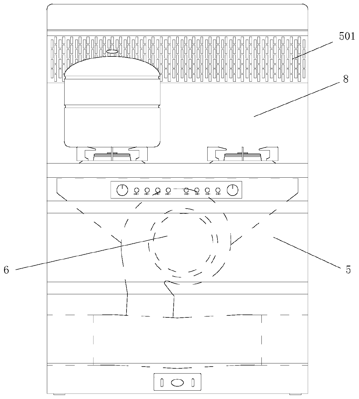
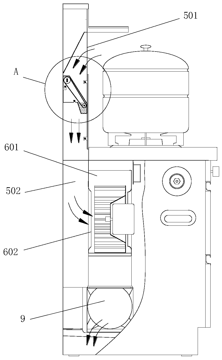
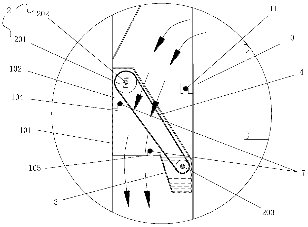
[0068] In order to make the purpose, technical solutions and advantages of the embodiments of the present invention more clear, the technical solutions in the embodiments will be clearly and completely described below in conjunction with the drawings in the embodiments of the present invention. The following embodiments are used to illustrate the present invention , but not to limit the scope of the present invention.

[0069] In the description of the present invention, it should be noted that the terms "upper", "lower", "front", "rear", "left", "right", "vertical", "inner", "outer" etc. The indicated orientation or positional relationship is based on the orientation or positional relationship shown in the drawings, and is only for the convenience of describing the present invention and simplifying the description, rather than indicating or implying that the referred device or element must have a specific orientation, or in a specific orientation. construction and operation, ...


PUM


Abstract

The invention discloses an oil filtering device and an integrated cooker with the oil filtering device. The oil filtering device comprises a driving assembly, a containing groove and a filtering part.The driving assembly is connected with the filtering part and drives the filtering part to circularly pass through the containing groove. A medium which can be attached to the surface of the filtering part and is used for treating lampblack is contained in the containing groove. The driving assembly comprises a driving part, a first rotating shaft and a second rotating shaft, the first rotating shaft is connected with the driving part, and the second rotating shaft is located in the containing groove. The dynamic oil filtering device is arranged in a negative pressure cavity of the integratedcooker, so that harmful substances such as grease in lampblack of the integrated cooker are efficiently intercepted, and the situation in which the lampblack suction effect of a range hood is reduceddue to the fact that the grease enters a volute and then is attached to an impeller of the range hood is prevented; the trouble that a user needs to periodically clean the impeller of the range hoodto keep the oil suction effect of the range hood is eliminated; the emission of harmful substances in the lampblack to the atmosphere is reduced; and the oil filtering device is arranged in an independent modular mode and is convenient to disassemble and assemble.

Description

technical field [0001] The invention belongs to the technical field of household electrical appliances, and in particular relates to an oil filter device and an integrated stove with the oil filter device. Background technique [0002] The integrated stove is a combined cooker that integrates multiple functions such as range hood, gas stove, disinfection cabinet, and storage cabinet. It mainly includes a cabinet, a stove installed on the cabinet, and an oil baffle on the top of the stove And the oil filter screen, the combustion system located under the stove and the air duct connected to the suction port and other components. In actual use, only need to turn on the corresponding switch to make the combustion system, disinfection cabinet, etc. work. It has the advantages of simple installation, strong integrity, and better oil fume extraction effect. [0003] The Chinese patent with the application number CN201910420447.7 discloses an oil filter installation structure and a...

Claims


Application Information

Patent Timeline
Patent Type & Authority Applications(China)
IPC IPC(8): B01D47/02B01D53/14F24C15/20
CPCB01D47/028B01D53/1487F24C15/2035
Inventor 付成冲邓鹏飞龚东巧王秀飞李承鹏王善旭
Owner QINGDAO HAIER WISDOM KITCHEN APPLIANCE CO LTD
Why Eureka
Try Eureka