Waste gas purification treatment equipment
A technology for treatment equipment and waste gas purification, applied in gas treatment, chemical/physical processes, chemical instruments and methods, etc., can solve problems such as toxicity and environmental pollution, and achieve the effect of improving degradation ability, simple equipment and good purification effect
- Summary
- Abstract
- Description
- Claims
- Application Information
AI Technical Summary
Problems solved by technology
Method used
Image

Examples
Embodiment 1
[0023] Such as Figure 1-2 As shown, the present invention provides a kind of technical scheme:
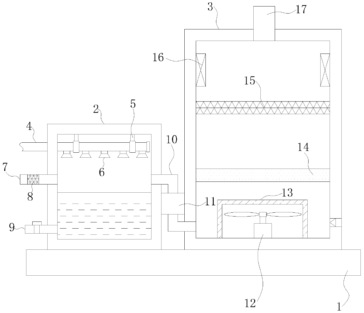
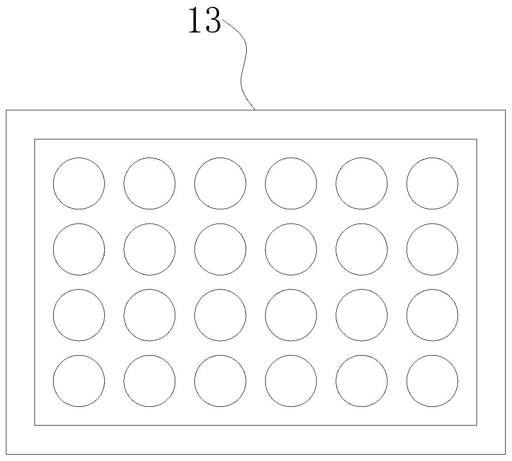
[0024] A kind of exhaust gas purification treatment equipment, comprising a bottom plate 1, a humidification chamber 2 is fixedly connected to the top left side of the bottom plate 1, a water storage tank is arranged inside the humidification chamber 2, a water outlet pipe 9 is arranged on the left side of the bottom of the humidification chamber 2, and the water outlet pipe 9 It communicates with the water storage tank, the outside of the outlet pipe 9 is provided with a switch valve 1, the right side of the top of the bottom plate 1 is fixedly connected with the treatment chamber 3, the lower right corner of the treatment chamber 3 is provided with a one-way air hole, the top of the bottom plate 1 is provided with the water inlet pipe 4, and the water inlet pipe 4 runs through the humidification chamber 2 and extends to the interior of the humidification chamber 2, the outer sur...
Embodiment 2
[0034] Such as Figure 1-2 As shown, the present invention provides a kind of technical scheme:
[0035]A kind of exhaust gas purification treatment equipment, comprising a bottom plate 1, a humidification chamber 2 is fixedly connected to the top left side of the bottom plate 1, a water storage tank is arranged inside the humidification chamber 2, a water outlet pipe 9 is arranged on the left side of the bottom of the humidification chamber 2, and the water outlet pipe 9 It communicates with the water storage tank, the outside of the outlet pipe 9 is provided with a switch valve 1, the right side of the top of the bottom plate 1 is fixedly connected with the treatment chamber 3, the lower right corner of the treatment chamber 3 is provided with a one-way air hole, the top of the bottom plate 1 is provided with the water inlet pipe 4, and the water inlet pipe 4 runs through the humidification chamber 2 and extends to the interior of the humidification chamber 2, the outer surf...
Embodiment 3
[0045] Such as Figure 1-2 As shown, the present invention provides a kind of technical scheme:
[0046] A kind of exhaust gas purification treatment equipment, comprising a bottom plate 1, a humidification chamber 2 is fixedly connected to the top left side of the bottom plate 1, a water storage tank is arranged inside the humidification chamber 2, a water outlet pipe 9 is arranged on the left side of the bottom of the humidification chamber 2, and the water outlet pipe 9 It communicates with the water storage tank, the outside of the outlet pipe 9 is provided with a switch valve 1, the right side of the top of the bottom plate 1 is fixedly connected with the treatment chamber 3, the lower right corner of the treatment chamber 3 is provided with a one-way air hole, the top of the bottom plate 1 is provided with the water inlet pipe 4, and the water inlet pipe 4 runs through the humidification chamber 2 and extends to the interior of the humidification chamber 2, the outer sur...
PUM
 Abstract
Description
Claims
Application Information
 - R&D
- Intellectual Property
- Life Sciences
- Materials
- Tech Scout
- Unparalleled Data Quality
- Higher Quality Content
- 60% Fewer Hallucinations
Browse by: Latest US Patents, China's latest patents, Technical Efficacy Thesaurus, Application Domain, Technology Topic, Popular Technical Reports.
© 2025 PatSnap. All rights reserved.Legal|Privacy policy|Modern Slavery Act Transparency Statement|Sitemap|About US| Contact US: help@patsnap.com