Hollow fiber membrane filter element and packaging method thereof

A fiber membrane and hollow technology, which is applied in the field of filter membranes, can solve the problems of large difference in length between the inside and outside of hollow fiber membranes, uneven flow of hollow fiber membrane filter elements, and uneven filling of hollow fiber membrane filaments, etc., to achieve uniform water channel balance and reduce Adhesion phenomenon, the effect of reducing the difference

Active Publication Date: 2020-07-10
NINGBO FOTILE KITCHEN WARE CO LTD
View PDF8 Cites 6 Cited by
  • Summary
  • Abstract
  • Description
  • Claims
  • Application Information

AI Technical Summary

Problems solved by technology

[0002] Hollow fiber membrane household water purifier components generally include a filter housing and a hollow fiber membrane located in the filter housing. The hollow fiber membrane is mostly in the form of a U-shaped sealing assembly, but this method has the following problems: First, the length difference between the inside and outside of the hollow fiber membrane It is large, and there is a lot of waste in production and removal (U-shaped center and outside), which wastes resources; secondly, the U-shaped is wrapped with a mesh sleeve, so that the hollow fiber membranes are tightly bonded. Under the action of pollutants and pressure in the water, the internal hollow fiber membranes cannot be effectively Utilization; finally, the U-shape is wrapped with a mesh sleeve, so that the hollow fiber membrane is tightly bonded, the filling of the hollow fiber membrane is uneven, and the flow of the external pressure hollow fiber membrane filter element is uneven, resulting in concentration polarization, which cannot effectively filter and desalinate

Method used


Image

  • Hollow fiber membrane filter element and packaging method thereof
  • Hollow fiber membrane filter element and packaging method thereof
  • Hollow fiber membrane filter element and packaging method thereof

Examples


Embodiment Construction

[0040] The present invention will be further described in detail below in conjunction with the accompanying drawings and embodiments.

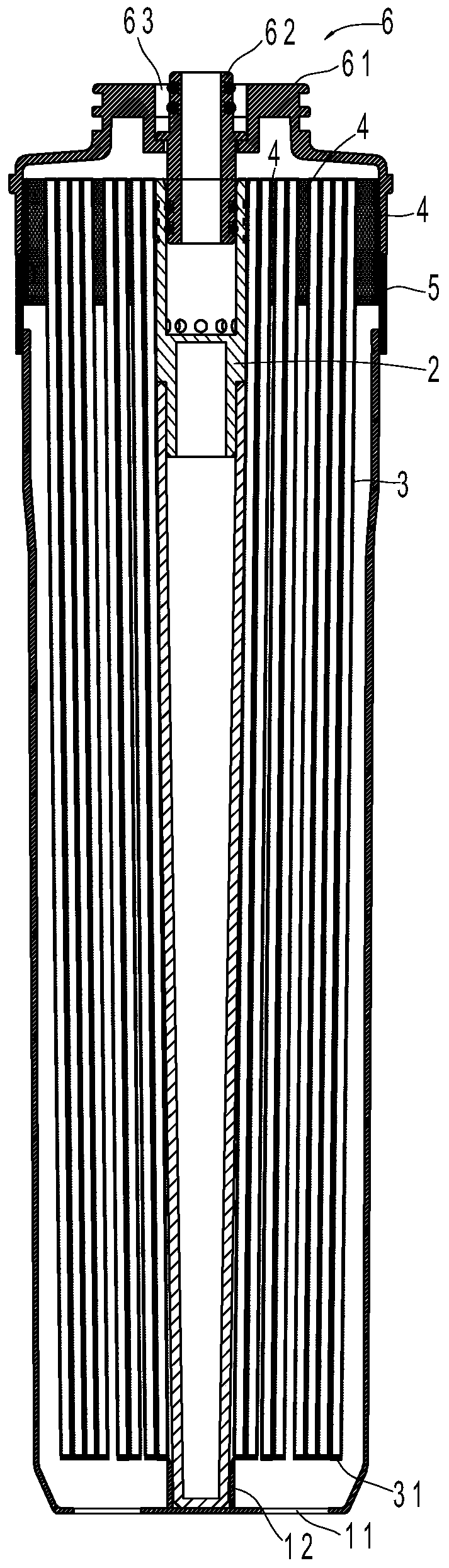
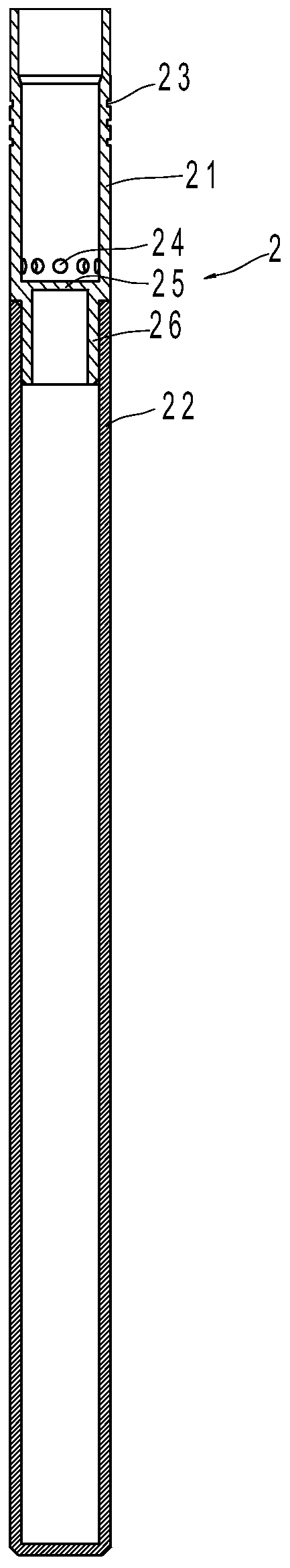
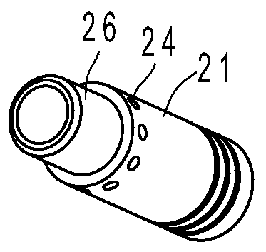
[0041] Such as Figure 1 to Figure 5 As shown, the hollow fiber membrane filter element in this embodiment includes a filter housing 1 , a central tube 2 , a hollow fiber membrane 3 , a sealing shell 5 , a sealing layer 4 and a water collecting cover 6 . The upper end of the filter housing 1 forms an opening, and a dirty water outlet hole 11 is opened on the bottom plate; the central pipe 2 is arranged in the middle of the filter housing 1, and one end is opened to form a water inlet port, and a water distribution hole 24 is opened on the side wall.

[0042] The hollow fiber membrane 3 is bundled, located in the filter housing 1, and the first end is evenly coated on the outer periphery of the water inlet port of the central tube 2, and the second end is arranged along the length direction of the central tube 2, near the bottom end of the cent...


PUM


Abstract

A hollow fiber membrane filter element is characterized in that the filter element comprises a filter shell, a central pipe, hollow fiber membranes, a glue sealing shell, glue sealing layers and a water collecting cover; an opening is formed in the upper end of the filter shell, and a dirty water outlet hole is formed in a bottom plate; the central pipe is arranged in the middle of the filter shell, one end is opened to form a water inlet port, and water distribution holes are formed in the side wall; the hollow fiber membranes are positioned in the filter shell, first ends of the hollow fibermembrane uniformly coat the periphery of the water inlet port of the central pipe, and second ends of the hollow fiber membranes are arranged in the length direction of the central pipe and close tothe bottom end of the central pipe; the glue sealing shell is arranged on the periphery of the opening of the filter shell; and the glue sealing layers are positioned between the inner wall of the glue sealing shell and the hollow fiber membranes, between the hollow fiber membranes and between the hollow fiber membranes and the outer wall of the central pipe. The invention further discloses a gluesealing method for the hollow fiber membrane filter element. The method has the advantages of more uniform inlet water distribution and reduction of membrane filament concentration polarization.

Description

technical field [0001] The invention relates to a filter membrane, in particular to a packaging method for the filter membrane. Background technique [0002] Hollow fiber membrane household water purifier components generally include a filter housing and a hollow fiber membrane located in the filter housing. The hollow fiber membrane is mostly in the form of a U-shaped sealing assembly, but this method has the following problems: First, the length difference between the inside and outside of the hollow fiber membrane It is large, and there is a lot of waste in production and removal (U-shaped center and outside), which wastes resources; secondly, the U-shaped is wrapped with a mesh sleeve, so that the hollow fiber membranes are tightly bonded. Under the action of pollutants and pressure in the water, the internal hollow fiber membranes cannot be effectively Utilization; finally, the U-shape is wrapped with a mesh sleeve, so that the hollow fiber membrane is tightly bonded, t...

Claims


Application Information

Patent Timeline
Patent Type & Authority Applications(China)
IPC IPC(8): B01D63/02
CPCB01D63/02B01D63/022
Inventor 王强倪澄峰
Owner NINGBO FOTILE KITCHEN WARE CO LTD
Why Eureka
Try Eureka