
Iron filing collection device for machining

A collection device and machining technology, applied in metal processing equipment, metal processing mechanical parts, manufacturing tools, etc., can solve the problems of low recycling efficiency and inability to achieve cooling flood treatment of iron filings, so as to facilitate centralized processing and improve follow-up Processing efficiency, the effect of promoting rapid cooling

Inactive Publication Date: 2020-07-10
陈思涵
View PDF13 Cites 4 Cited by
  • Summary
  • Abstract
  • Description
  • Claims
  • Application Information

AI Technical Summary

Problems solved by technology

Although the device can realize the collection and transportation of iron filings, the iron filings cannot be fully cooled and processed, resulting in low recycling efficiency. Therefore, a kind of iron filings collection device for machining is now provided to solve the above problems. technical problem

Method used


Image

  • Iron filing collection device for machining
  • Iron filing collection device for machining
  • Iron filing collection device for machining

Examples


Embodiment 1

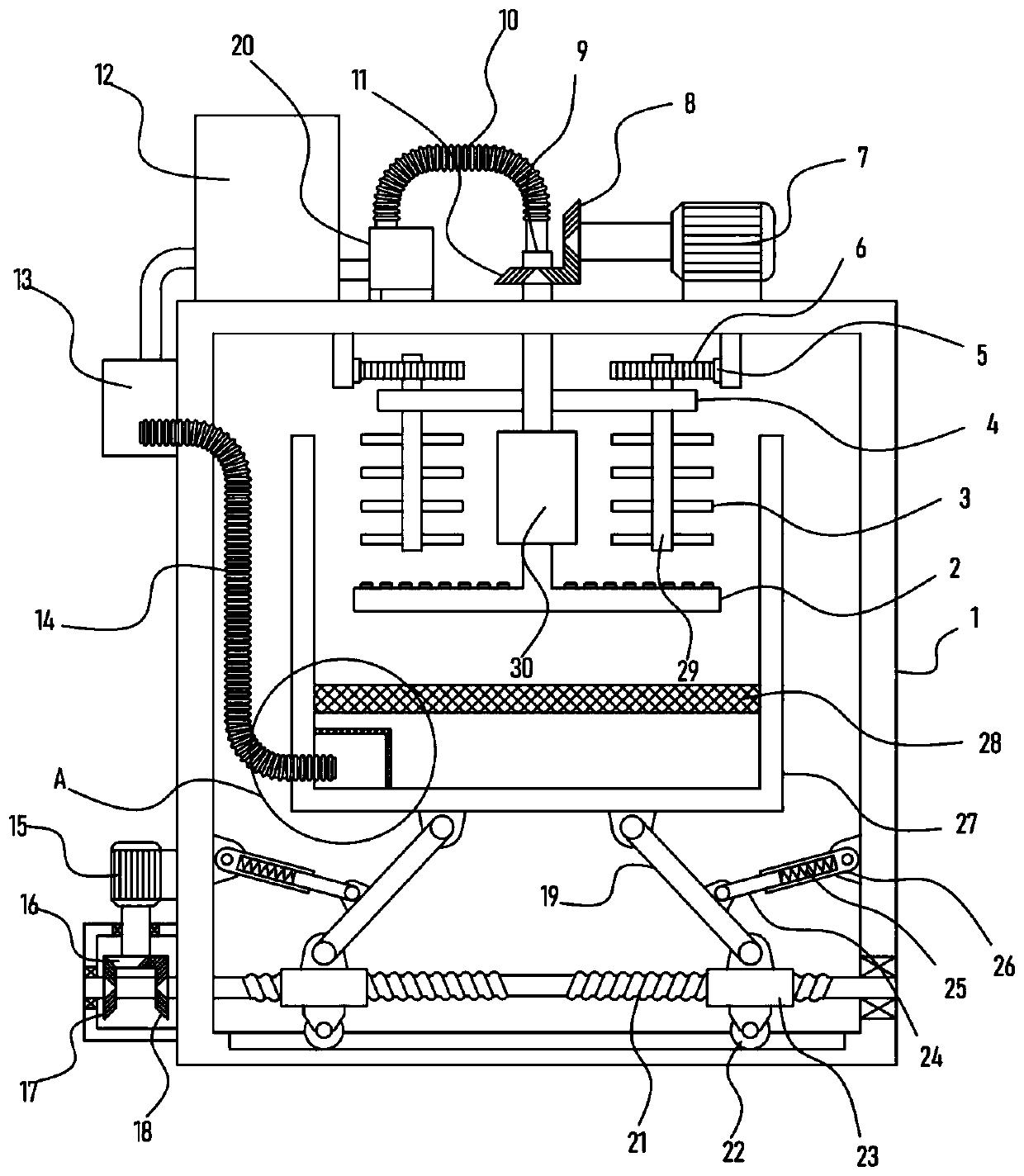
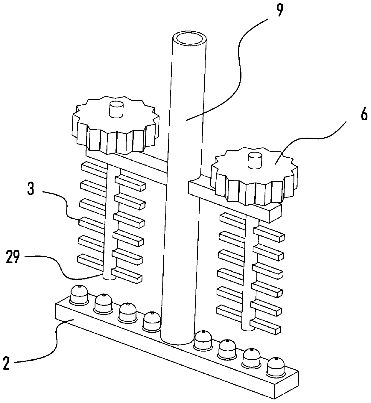
[0024] see Figure 1-3 , a chip collecting device for machining, comprising a support frame 1, a coolant tank 12 is fixed on the support frame 1, a storage tank 27 is provided in the support frame 1, a driving mechanism is provided on the support frame 1, and the The mechanism drives and rotates a rotating tube 9 extending into the storage tank 27. A dispersing mechanism is provided on the rotating tube 9. An electromagnet 30 is fixed on the rotating tube 9. The bottom of the rotating tube 9 is installed with a coolant tank. 12 communicates with the cooling mechanism provided, the side wall of the support frame 1 is fixed with a driving motor II15, a reversing mechanism is connected to the driving motor II15, and a lifting mechanism is connected between the reversing mechanism and the storage tank 27.

[0025] The inside of the storage tank 27 in this device is used to store the iron filings produced in the machining process. The electromagnet 30 is energized to absorb the iro...

Embodiment 2

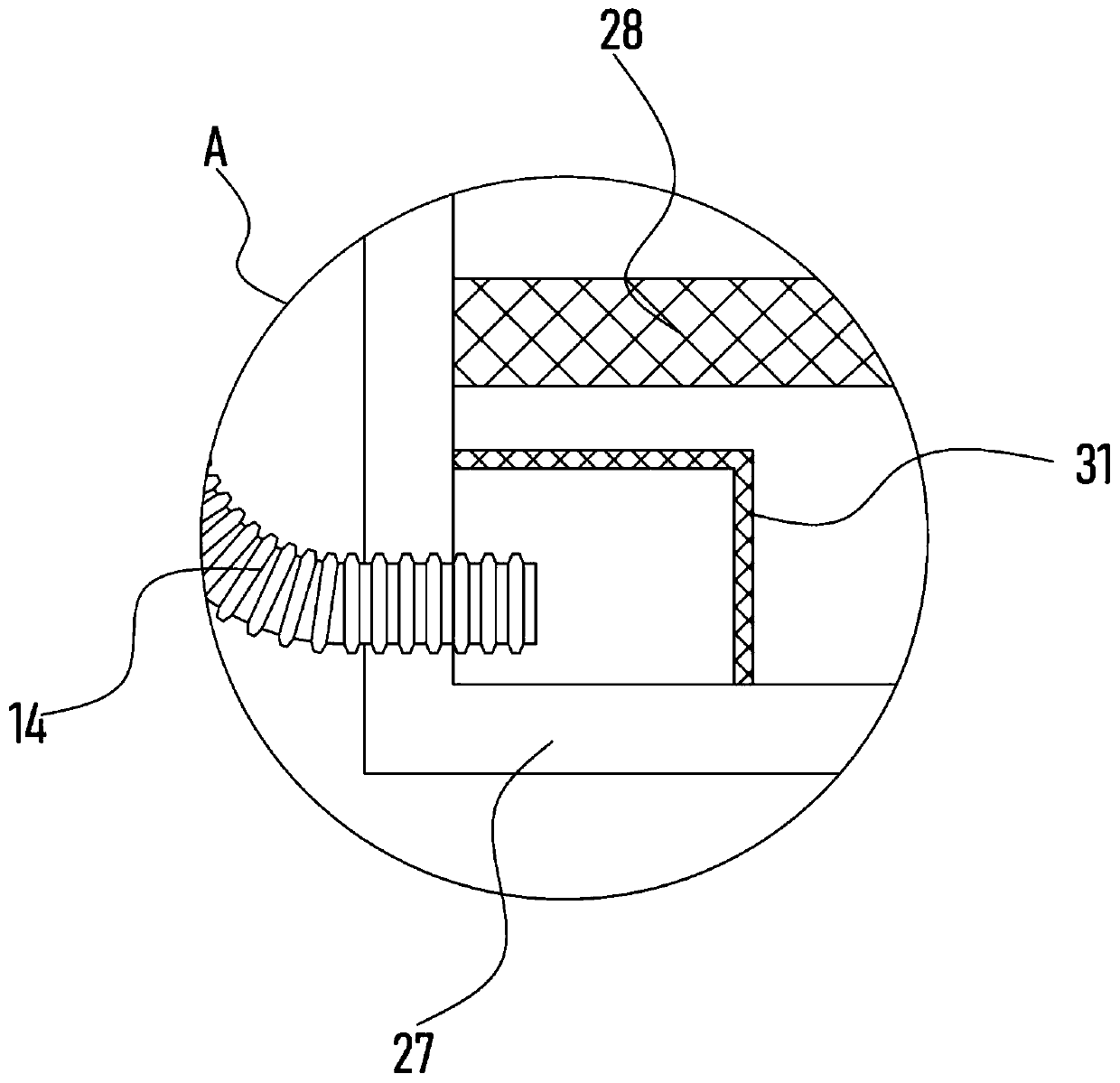
[0031] On the basis of Embodiment 1, in addition, the side wall of the support frame 1 is fixed with a lift pump 13 communicating with the coolant tank 12, and the inlet end of the lift pump 13 communicates with the storage tank 27 through the bellows II14, and the storage tank 27 is horizontally fixed with The mesh plate 28 above the bellows II14 is located at one end of the bellows II14 in the storage tank 27 and is provided with a filter screen cover 31 .

[0032] The cooling liquid sprayed from the spray plate 2 can pass through the mesh of the mesh plate 28 and drop to the bottom of the storage tank 27, and the lift pump 13 is set to extract and recover the cooling liquid in the storage tank 27 through the bellows II14 to the cooling liquid Inside the box 12, the circulation effect is realized, the circulation utilization of the coolant is guaranteed, and the sufficient cooling of the high-temperature iron filings is promoted.

[0033] Further, the device is also provided...


PUM


Abstract

The invention discloses an iron filing collection device for machining, and relates to the technical field of iron filing processing. The iron filing collection device includes a supporting frame, a cooling liquid tank is fixed to the supporting frame, a storage tank is arranged in the supporting frame, and a driving mechanism is arranged on the supporting frame; and the driving mechanism drives arotating tube extending into the storage tank to rotate, a drive motor II is connected with a reversing mechanism, and a lifting mechanism is connected between the reversing mechanism and the storagetank. Iron filings in the storage tank are adsorbed and collected through an electromagnet, and a spray disc in a cooling mechanism can spray cooling liquid to the iron filings in the storage tank topromote the cooling effect of the iron filings at higher temperature; and a stirring blade in a dispersing mechanism can rotate around a rotating shaft and revolve around the rotating tube, the fulldispersion of the iron filings is effectively improved, the rapid cooling of the iron filings is promoted, the centralized treatment of the iron filings after collection is facilitated, and the subsequent processing efficiency of the iron filings is improved.

Description

technical field [0001] The invention relates to the technical field of iron filings processing, in particular to an iron filings collection device for machining. Background technique [0002] Machining refers to the process of changing the shape or performance of a workpiece through a mechanical device. According to the difference in processing methods, it can be divided into cutting processing and pressure processing. The production process of the machine refers to the whole process of making products from raw materials. For machine production, it includes transportation and storage of raw materials, production preparation, blank manufacturing, processing and heat treatment of parts, product assembly, debugging, painting and packaging, etc. The content of the production process is very extensive. Modern enterprises use the principles and methods of systems engineering to organize and guide production, and regard the production process as a production system with input and ...

Claims


Application Information

Patent Timeline
Patent Type & Authority Applications(China)
IPC IPC(8): B23Q11/00B23Q11/10
CPCB23Q11/0046B23Q11/0067B23Q11/1069
Inventor 薛炜烨陈思涵
Owner 陈思涵
Learn More