
Automobile exhaust pipe manufacture welding treatment process

A technology for automobile exhaust and treatment process, which is applied in the direction of manufacturing tools, grinding workpiece supports, metal processing equipment, etc., can solve the problems of reducing the efficiency of grinding, unable to adjust the angle, reducing the effect of grinding, etc., to improve the efficiency of grinding , Improve contact tightness and reduce the effect of working steps

Active Publication Date: 2020-07-10
江苏佳泰汽车配件有限公司
View PDF5 Cites 2 Cited by
  • Summary
  • Abstract
  • Description
  • Claims
  • Application Information

AI Technical Summary

Problems solved by technology

[0005] The present invention can solve the problem that the existing equipment cannot adjust the angle during grinding when cleaning the welding spatula generated during the welding of the muffler and the connecting pipe in the automobile exhaust pipe, and it is easy to cause the equipment to be unable to perfectly cooperate with the spatula. As a result, the removal of the welding spar is not clean, which reduces the effect of grinding. At the same time, the two connecting pipes cannot be cleaned at the same time, thereby reducing the efficiency of grinding. In addition, it is impossible to clean the surface of the connecting pipe without changing the position of the connecting pipe. Remove the weld bead generated in the local area, thus increasing the steps of welding bead grinding and reducing the efficiency of grinding and other problems

Method used


Image

  • Automobile exhaust pipe manufacture welding treatment process
  • Automobile exhaust pipe manufacture welding treatment process
  • Automobile exhaust pipe manufacture welding treatment process

Examples


Embodiment Construction

[0035] The embodiments of the present invention will be described in detail below with reference to the accompanying drawings, but the present invention can be implemented in many different ways defined and covered by the claims.

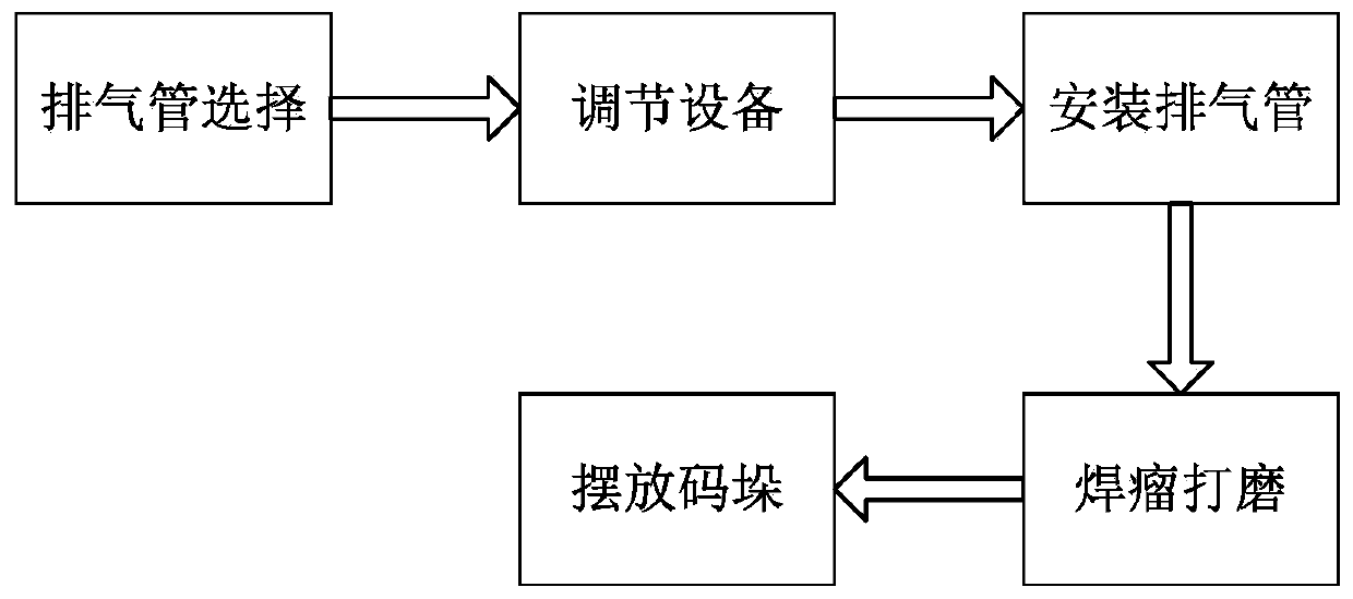
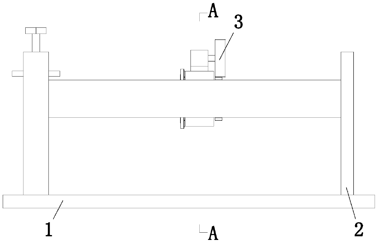
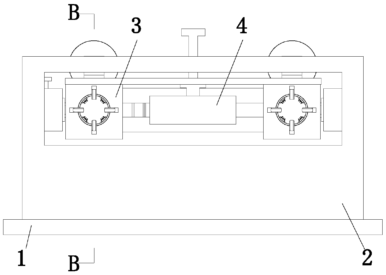
[0036] Such as Figure 1 to Figure 8As shown, in order to achieve the above object, the present invention adopts the following technical solutions, a welding process for manufacturing automobile exhaust pipes, which uses a welding processing device for automobile exhaust pipes, and the welding processing device for automobile exhaust pipes includes a base plate 1 , receiving device 2, grinding device 3 and adjusting device 4, when adopting above-mentioned automobile exhaust pipe welding processing device to process the automobile exhaust pipe welding place, the specific method is as follows:

[0037] S1. Exhaust pipe selection: manually select the exhaust pipe after welding, and remove the stains and other residues on the surface of the exhaust pipe...


PUM


Abstract

The invention relates to an automobile exhaust pipe manufacture welding treatment process. A bottom plate, a bearing and containing device, polishing devices and a regulation device are included. Thebearing and containing device is installed at the upper end of the bottom plate. The polishing devices are symmetrically arranged in the middle of the bearing and containing device. The polishing devices are connected with the bearing and containing device in a sliding fit manner. The automobile exhaust pipe manufacture welding treatment process can solve the problem that when an existing device conducts cleaning for weld beadings generated during welding of silencers in automobile exhaust pipes and connection pipes, angle regulation cannot be conducted during polishing, the situation that thedevice cannot be perfectly matched with the weld beadings is likely to be caused, and therefore removal of the weld beadings is not complete and the polishing effect is reduced, the problem that dueto the fact that the two connection pipes cannot be cleaned at the same time, the polishing efficiency is reduced and the problem that due to the fact that weld beadings generated on the other placesof the surfaces of the connection pipes cannot be removed under the condition of not changing the positions of the connection pipes, the weld beading polishing steps are increased and the polishing efficiency is reduced.

Description

technical field [0001] The invention relates to the technical field of exhaust pipe welding, in particular to a manufacturing and welding process for automobile exhaust pipes. Background technique [0002] The automobile exhaust pipe is a part of the engine exhaust system. The exhaust system mainly includes the exhaust manifold, the exhaust pipe and the muffler. Generally, the three-stage catalytic converter for controlling the emission of engine pollutants is also installed in the exhaust system. The trachea generally includes a front exhaust pipe and a rear exhaust pipe, and its main material is stainless steel SUS304. The exhaust pipe mainly plays the role of shock absorption and noise reduction for the car body, and prolongs the life of the exhaust muffler system. [0003] At present, when the existing welding welds produced during the welding of the muffler and the connecting pipe in the automobile exhaust pipe are cleaned, there are usually the following deficiencies: ...

Claims


Application Information

Patent Timeline
IPC IPC(8): B24B9/04B24B27/033B24B27/00B24B55/00B24B41/06B24B41/00B24B47/12B24B41/02
CPCB24B9/04B24B27/0076B24B27/033B24B41/005B24B41/02B24B41/06B24B47/12B24B55/00
Inventor 黄伟付子豪
Owner 江苏佳泰汽车配件有限公司
Learn More