
Aluminum alloy hub positioning clamp

A technology of aluminum alloy wheels and positioning fixtures, which is applied in the direction of manufacturing tools, workpiece clamping devices, worktables, etc., can solve the problems of material waste, increase the time for adjusting equipment and process parameters, increase labor intensity of workers, etc., and achieve convenient use , a wide range of use, the effect of reducing labor intensity

Inactive Publication Date: 2020-07-10
王光银
View PDF7 Cites 16 Cited by
  • Summary
  • Abstract
  • Description
  • Claims
  • Application Information

AI Technical Summary

Problems solved by technology

[0003] When the current aluminum alloy wheels are processed, they are generally clamped and positioned with the help of external fixtures to facilitate other processes such as grinding, polishing, and drilling. In the traditional aluminum alloy wheel processing technology, the fixtures are the same size as the wheel hub. One-to-one correspondence and dedicated, that is to say, before processing wheels of different sizes, it is necessary to select the corresponding positioning fixture according to the type and size of the wheel, and also need to adjust the accuracy of the replaced fixture, which not only increases It saves the time to adjust the equipment and process parameters when changing the wheel hub, increases the labor intensity of workers, and also causes waste of materials due to too many fixture specifications. There are certain limitations in the scope of application.

Method used


Image

  • Aluminum alloy hub positioning clamp
  • Aluminum alloy hub positioning clamp
  • Aluminum alloy hub positioning clamp

Examples


Embodiment Construction

[0024] The following will clearly and completely describe the technical solutions in the embodiments of the present invention with reference to the accompanying drawings in the embodiments of the present invention. Obviously, the described embodiments are only some, not all, embodiments of the present invention. Based on the embodiments of the present invention, all other embodiments obtained by persons of ordinary skill in the art without making creative efforts belong to the protection scope of the present invention.

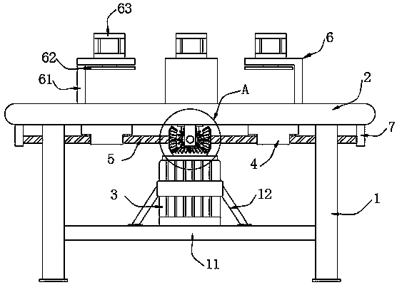
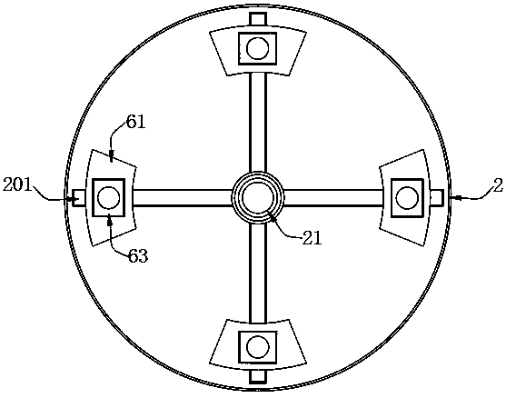
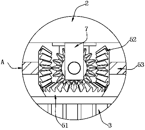
[0025] see Figure 1-5 , the present invention provides the following technical solutions: a positioning fixture for aluminum alloy wheels, including a bracket 1 and a positioning workbench 2 that is screwed and fixed at the top of the bracket 1; The middle position is screwed and fixed with a servo motor 3 by a motor mounting bracket 12, and the output end of the servo motor 3 is connected with a transmission mechanism 5. The transmission mechanism 5 includes...


PUM


Abstract

The invention belongs to the technical field of hub machining, and particularly relates to an aluminum alloy hub positioning clamp. The aluminum alloy hub positioning clamp comprises a support and a positioning workbench which is fixed to the top end of the support by threaded connection. A mounting base is fixedly arranged on the inner side of the bottom end of the support, and a servo motor is fixed to the middle of the top end of the mounting base through a motor mounting frame by threaded connection. Sliding grooves used for radial movement of clamping mechanisms are formed in the workbench. The servo motor is used for driving a driving gear to rotate at a high speed, so that four driven gears are driven to rotate. A screw rod is driven to rotate through the rotation of the driven gears, so that a linkage seat on the screw rod is driven to move on the screw rod. The four clamping mechanisms can axially move outwards or inwards on the positioning workbench. A hub placed on the positioning workbench is transversely clamped and positioned, and an air cylinder is used for driving a limiting clamping plate to move downwards, so that the hub is longitudinally clamped and positioned.The clamping stability is high, the clamp can be suitable for clamping and positioning hubs of different sizes, and the application range is wide.

Description

technical field [0001] The invention belongs to the technical field of wheel hub processing, and in particular relates to an aluminum alloy wheel hub positioning fixture. Background technique [0002] The hub, also known as the rim, is the barrel-shaped, center-mounted part of the tire that is used to support the tire. Common car wheels include steel wheels and aluminum alloy wheels. Steel wheels have high strength and are often used in large trucks; however, steel wheels are heavy and have a single shape, which does not conform to the current low-carbon and fashionable concept, and is gradually being replaced by aluminum alloy wheels. Wheels are divided into aluminum alloy wheels and steel wheels. Wheels, aluminum alloy wheels are divided into forging and casting. The fatigue strength and bending strength of forged aluminum alloy wheels are much higher than those of steel wheels. Under the same environment, the heat dissipation coefficient of aluminum alloy is three times ...

Claims


Application Information

Patent Timeline
Patent Type & Authority Applications(China)
IPC IPC(8): B25H1/08B25B11/00
CPCB25B11/00B25H1/08
Inventor 王春蕾张秀芹西风源侯辉
Owner 王光银
Learn More