
Automatic cutting plotter for end face of screw rod

A cutting plotter and end face technology, which is applied to engraving, conveyors, conveyor objects, etc., can solve problems such as the inability to guarantee the stability of the feeding operation, the inability to guarantee the continuity of the operation, and the inability to guarantee the stability of the workpiece, etc. It is convenient for automatic sliding and recycling, easy for automatic feeding and use, and it is conducive to the effect of safe operation.

Pending Publication Date: 2020-07-10
绵阳富林岚科技有限责任公司
View PDF0 Cites 3 Cited by
  • Summary
  • Abstract
  • Description
  • Claims
  • Application Information

AI Technical Summary

Problems solved by technology

[0008] The purpose of the present invention is to provide a screw end face automatic lettering machine to solve the problem that the current screw end face lettering machine proposed by the above-mentioned background technology cannot guarantee the stability of the feeding operation, the continuity of the operation, and the processing. The stability of the workpiece during the operation is not conducive to ensuring the safety of the operation

Method used


Image

  • Automatic cutting plotter for end face of screw rod
  • Automatic cutting plotter for end face of screw rod
  • Automatic cutting plotter for end face of screw rod

Examples


Embodiment Construction

[0041] The following will clearly and completely describe the technical solutions in the embodiments of the present invention with reference to the accompanying drawings in the embodiments of the present invention. Obviously, the described embodiments are only some, not all, embodiments of the present invention. Based on the embodiments of the present invention, all other embodiments obtained by persons of ordinary skill in the art without making creative efforts belong to the protection scope of the present invention.

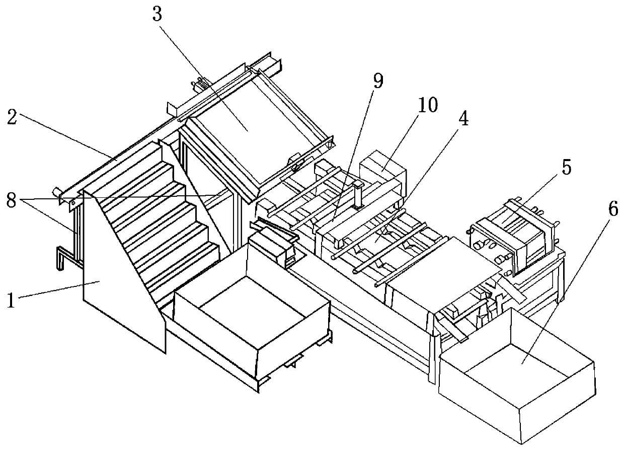
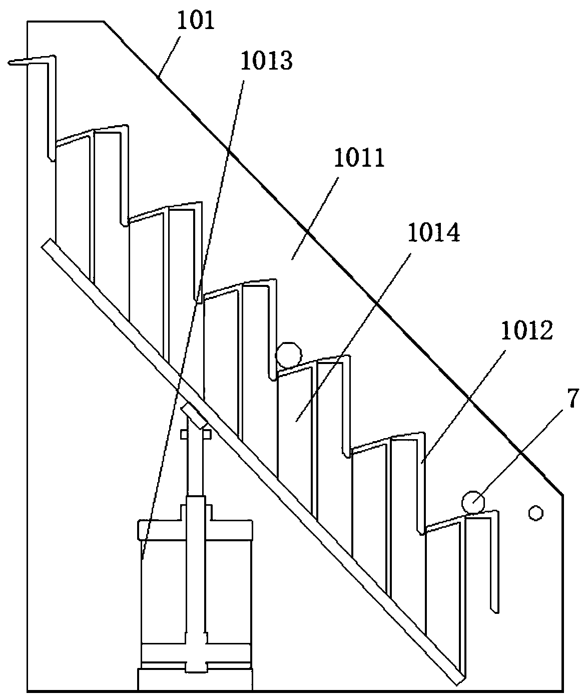
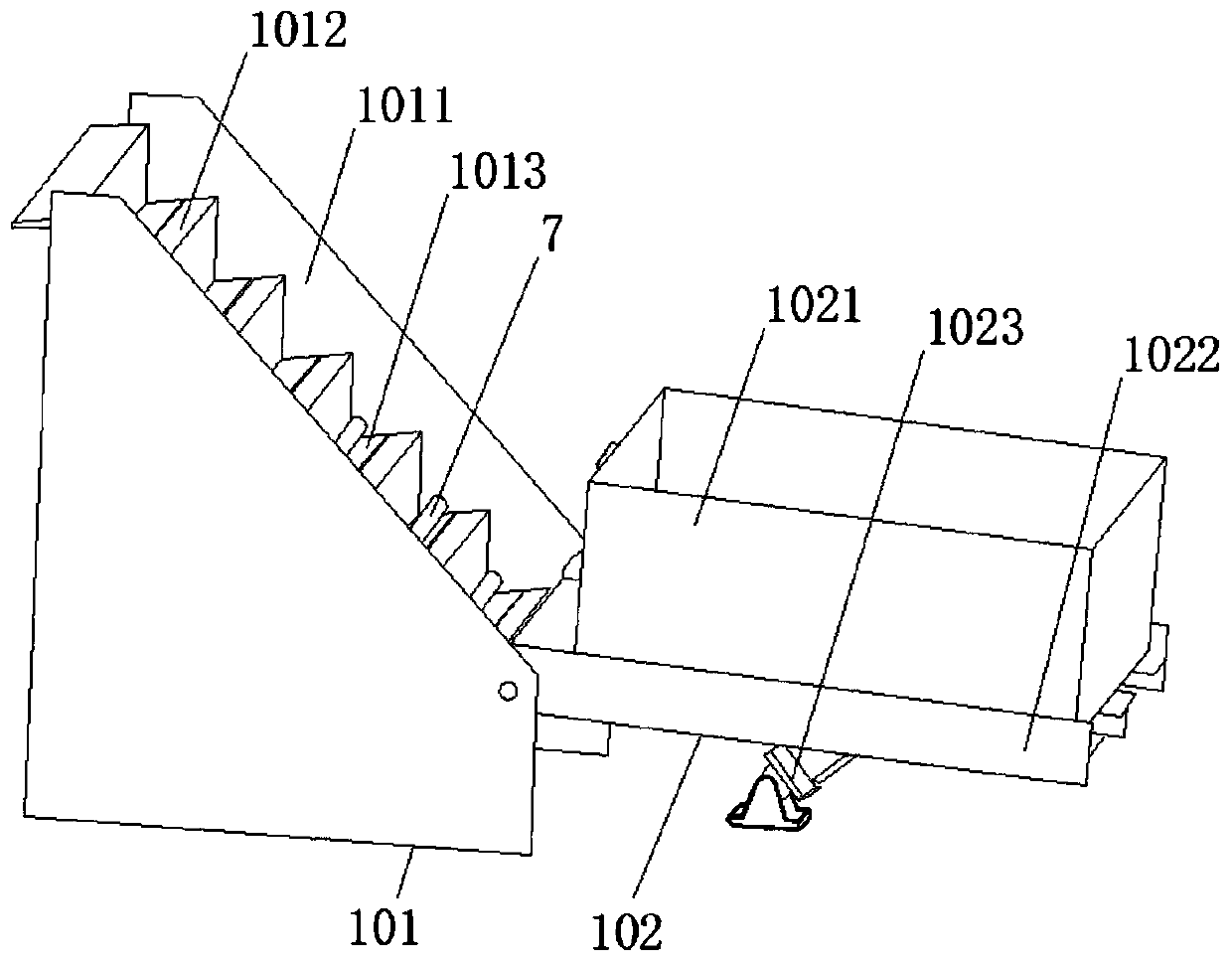
[0042]see Figure 1-15 , the present invention provides a technical solution: a screw end face automatic lettering machine, comprising an automatic feeding device 1, a fixed-distance conveying device 4, a workpiece 7, a support frame system 8 and a center hole station 10, and the automatic feeding device 1 The top end is connected with a transmission line 2, and the automatic feeding device 1 includes a ladder feeding mechanism 101 and an automatic tipping buc...


PUM


Abstract

The invention discloses an automatic cutting plotter for an end face of a screw rod. The automatic cutting plotter comprises an automatic feeding device, a fixed-distance conveying device, workpieces,a supporting frame system and a center hole station, the top end of the automatic feeding device is connected with a transmission line and comprises a stepped feeding mechanism and an automatic hopper tipping mechanism, the automatic hopper tipping mechanism comprises a hopper, a turning plate and an overturning power device, the hopper is fixedly mounted on the top face of the turning plate, a finished product box is arranged below the tail end of the fixed-distance conveying device, a compressing mechanism is mounted above the top end of the fixed-distance conveying device, the workpieces are placed in the hopper, and the compressing mechanism is composed of a fourth base plate, a third air cylinder and a pressure head. According to the automatic cutting plotter for the end face of thescrew rod, orderly and stable feeding can be ensured, separation of workpiece individuals can be ensured, the operation continuity is ensured conveniently, the stability of workpiece machining can beensured, and thus safe operation is facilitated.

Description

technical field [0001] The invention relates to the technical field of end face automatic lettering machines, in particular to a screw end face automatic lettering machine. Background technique [0002] With the development of industrial automation technology, most of the previous product nameplate installations have been changed to engraving operations for products. Among them, when performing engraving operations on screws, due to the large number of them, most of them use automatic engraving machines for operation; [0003] But existing screw rod end face carving plotter, when carrying out use, though proposed a part of improvement, it still has certain drawbacks, as: [0004] 1. It is not convenient to automatically load the screw, and cannot ensure the orderly placement of the screw, and cannot guarantee the stability of the feeding operation; [0005] 2. It is not convenient to separate the screw monomers in an orderly manner, it is not convenient to ensure the proces...

Claims


Application Information

Patent Timeline
Patent Type & Authority Applications(China)
IPC IPC(8): B65G37/00B65G47/82B65G65/23B65G47/74B65G47/88B65G47/22B44B3/06
CPCB65G37/00B65G47/82B65G65/23B65G47/74B65G47/88B65G47/22B44B3/06B65G2201/0217
Inventor 李军李兵王务明
Owner 绵阳富林岚科技有限责任公司
Learn More