
Auxiliary rolling rake devices of unearthed belt of shield machine and use method

A technology of shield machine and rolling harrow, which is applied in the field of shield machine unearthed belt-assisted rolling harrow device, which can solve the problems of reducing construction efficiency, increasing labor intensity, and falling, so as to improve construction efficiency, reduce labor intensity, and efficiently transport Effect

Pending Publication Date: 2020-07-10
广州市力劲机电有限公司
View PDF0 Cites 1 Cited by
  • Summary
  • Abstract
  • Description
  • Claims
  • Application Information

AI Technical Summary

Problems solved by technology

The muck transport relies on the friction between each other and the belt to drive forward, and the muck is discharged from the screw conveyor to the belt conveyor. Since the belt section at the slag outlet of the screw conveyor is inclined, the muck under the gravity When the impact or the slump of the muck is too large, the sliding force is greater than the frictional force, and the muck is easy to slip on the belt, resulting in a drop phenomenon, especially the large pieces of muck are more likely to slide down along the inclined belt, resulting in belt conveyor failure. The phenomenon of not being able to effectively transport the muck greatly increases the labor intensity and reduces the construction efficiency, and the falling muck has caused great trouble to the construction environment of the shield tunneling site

Method used


Image

  • Auxiliary rolling rake devices of unearthed belt of shield machine and use method
  • Auxiliary rolling rake devices of unearthed belt of shield machine and use method
  • Auxiliary rolling rake devices of unearthed belt of shield machine and use method

Examples


Embodiment Construction

[0034] The following will clearly and completely describe the technical solutions in the embodiments of the present invention in conjunction with the accompanying drawings. Obviously, the described embodiments are only some of the embodiments of the present invention, not all of them. Based on the embodiments of the present invention, all other embodiments obtained by persons of ordinary skill in the art without making creative efforts belong to the protection scope of the present invention.

[0035] In the description of this patent, it is to be understood that the terms "center", "upper", "lower", "front", "rear", "left", "right", "vertical", "horizontal", The orientation or positional relationship indicated by "top", "bottom", "inner", "outer", etc. is based on the orientation or positional relationship shown in the drawings, and is only for the convenience of describing this patent and simplifying the description, rather than indicating or implying References to devices or...


PUM


Abstract

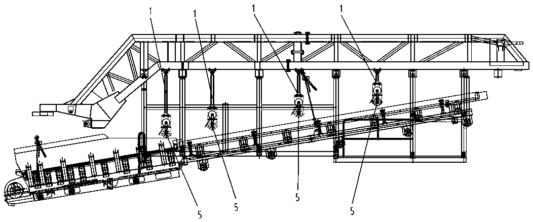
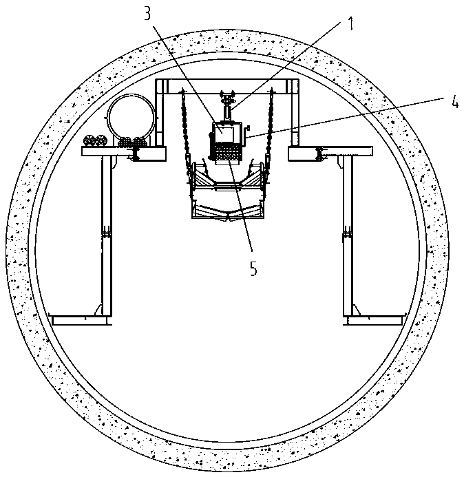
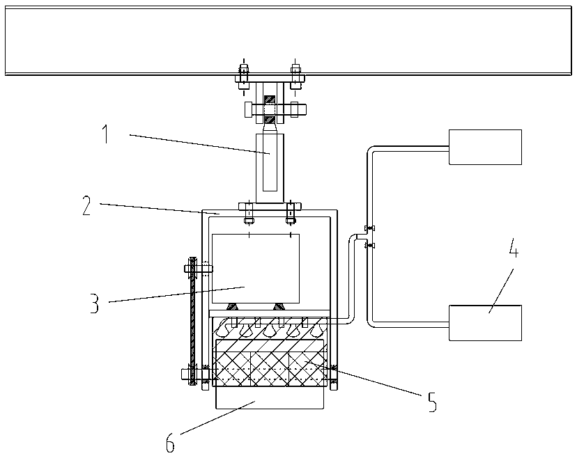
The invention discloses auxiliary rolling rake devices of an unearthed belt of a shield machine and a use method. The rolling rake devices are arranged on a bridge cross beam above the unearthed beltat intervals, and the arrangement track is parallel to the unearthed belt. Each rolling rake device comprises a hanging bracket, a hanging frame, a power device, a spraying device and a rolling rake,wherein each hanging bracket is connected to the bridge cross beam, the top end of each hanging frame is connected to the bottom of each hanging bracket, each hanging frame comprises an upper frame and a lower frame, each power device is arranged in the upper frame, each rolling rake is arranged in the lower frame and is connected with each power device, and each spraying device is connected to each hanging frame. According to the rolling rake devices, the plurality of rolling rake devices are arranged according to the shape of the belt to continuously boost slag soil, the rolling rakes are used as a driving force, and the spraying devices are used as an auxiliary power to push the massive slag soil to move upwards, so that the slag soil is prevented from rolling down and sliding downwards, the stable conveying of the slag soil to a horizontal belt conveyor is guaranteed, and the efficient conveying is carried out; and meanwhile, the construction environment is kept clean, the labor intensity is reduced, and the construction efficiency is improved.

Description

technical field [0001] The invention relates to the technical field of shield machine slag discharge, in particular to a shield machine excavation belt-assisted roller rake device and a use method thereof. Background technique [0002] As a kind of tunnel construction machine, the shield machine can be divided into two categories: earth pressure balance shield machine and mud water balance shield machine. Among them, the earth pressure balance shield machine is mainly suitable for soft soil stratum The soil is continuously cut, and the cut spoil is discharged by the screw conveyor, and the muck is transported to the soil bucket on the rear trolley by the belt conveyor, and then horizontally transported through the hole to the wellhead of the working pit and hoisted out. [0003] The earth pressure balance shield machine belt is divided into two parts, the inclined part and the horizontal part. The inclined part is the inclined belt section with a certain inclined angle under...

Claims


Application Information

Patent Timeline
IPC IPC(8): B65G47/82B65G47/16B65G53/00E21D9/12
CPCB65G47/16B65G47/82B65G53/00B65G2201/045E21D9/12
Inventor 张殿韶史海珠程忠成刘鑫
Owner 广州市力劲机电有限公司
Learn More