
Glass cutting and splitting processing method and device

A glass cutting and sheet processing technology, applied in glass cutting devices, glass production, glass manufacturing equipment, etc., can solve the problem that glass cannot be automatically cracked

Inactive Publication Date: 2020-07-10
深圳市青虹激光科技有限公司
View PDF4 Cites 9 Cited by
  • Summary
  • Abstract
  • Description
  • Claims
  • Application Information

AI Technical Summary

Problems solved by technology

[0006] In order to solve the above-mentioned problem that the glass cannot be automatically split after the watch cover is cut in the existing watch glass production process, the present invention provides a glass cutting and slicing processing method and device, which integrates the cutting and slicing processing of the watch cover glass into a circular cutting process , reduce the processing technology and increase the utilization rate of glass products

Method used


Image

  • Glass cutting and splitting processing method and device
  • Glass cutting and splitting processing method and device
  • Glass cutting and splitting processing method and device

Examples


Embodiment 1

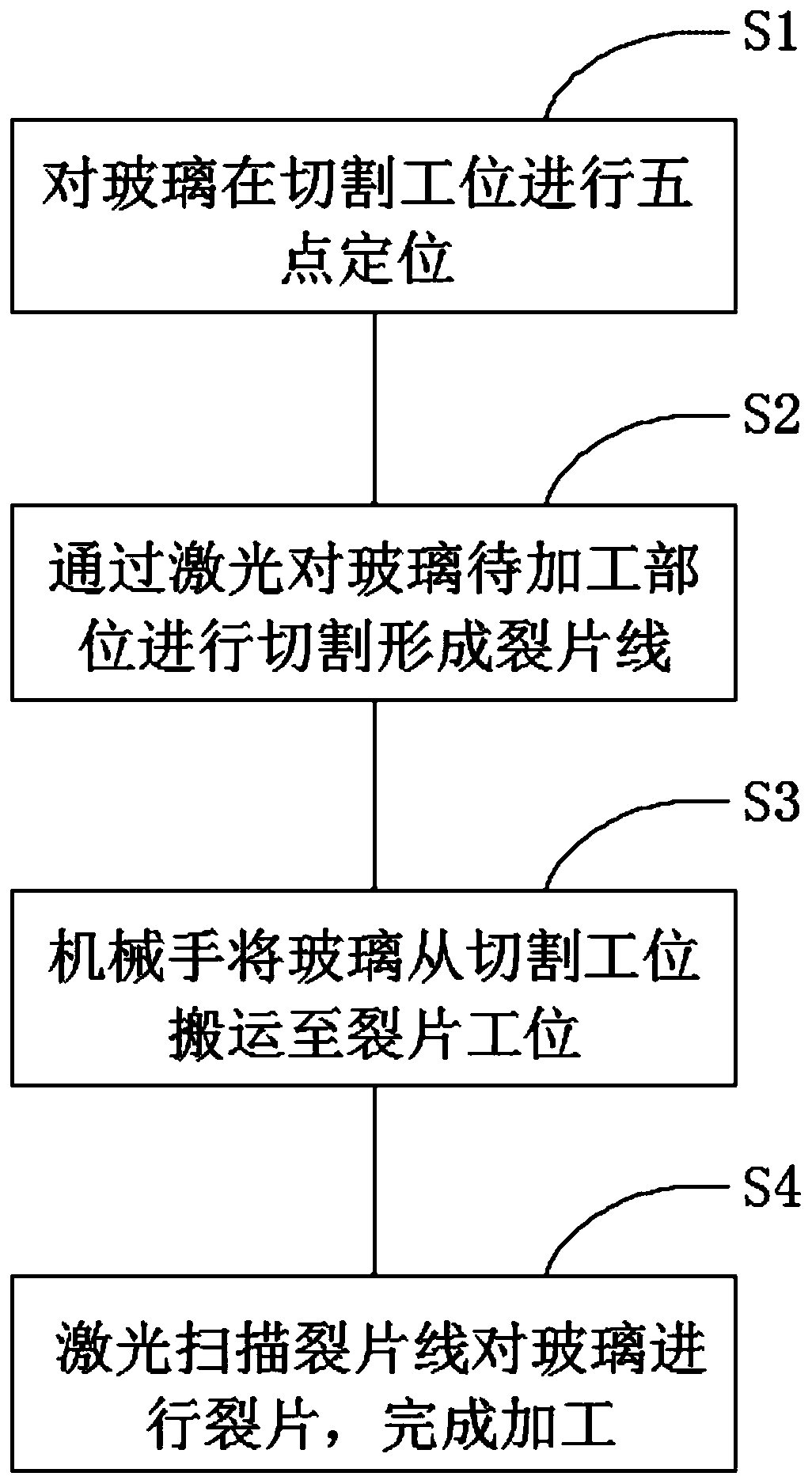
[0035] Such as figure 1 As shown, the present embodiment one provides a glass cutting slivers processing method,

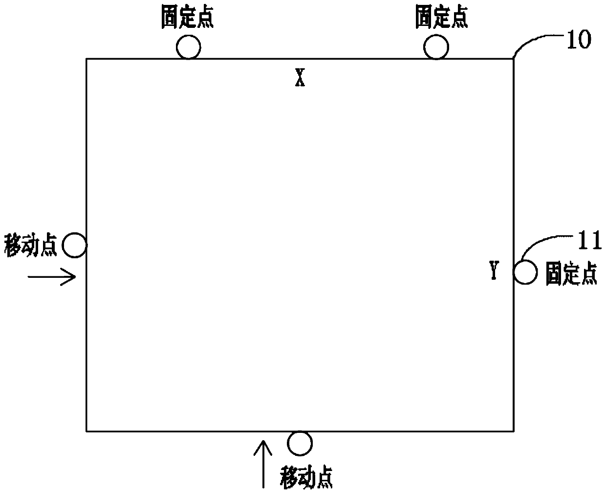
[0036] S101, performing five-point positioning on the cover glass at the cutting station;

[0037] S102, cutting and marking the cover glass according to the set trajectory to obtain a cutting line;

[0038] S103, the transplanting robot moves the cover glass from the cutting station to the split station;

[0039] S104. Generate laser thermal stress at the cutting line of the cover glass according to the set trajectory, so that the cut cover glass is split under the action of the laser thermal stress.

[0040] Wherein, the cutting tool used when cutting and scribing the cover glass includes an infrared laser; the laser used when generating laser thermal stress at the cutting line of the cover glass is a carbon dioxide laser.

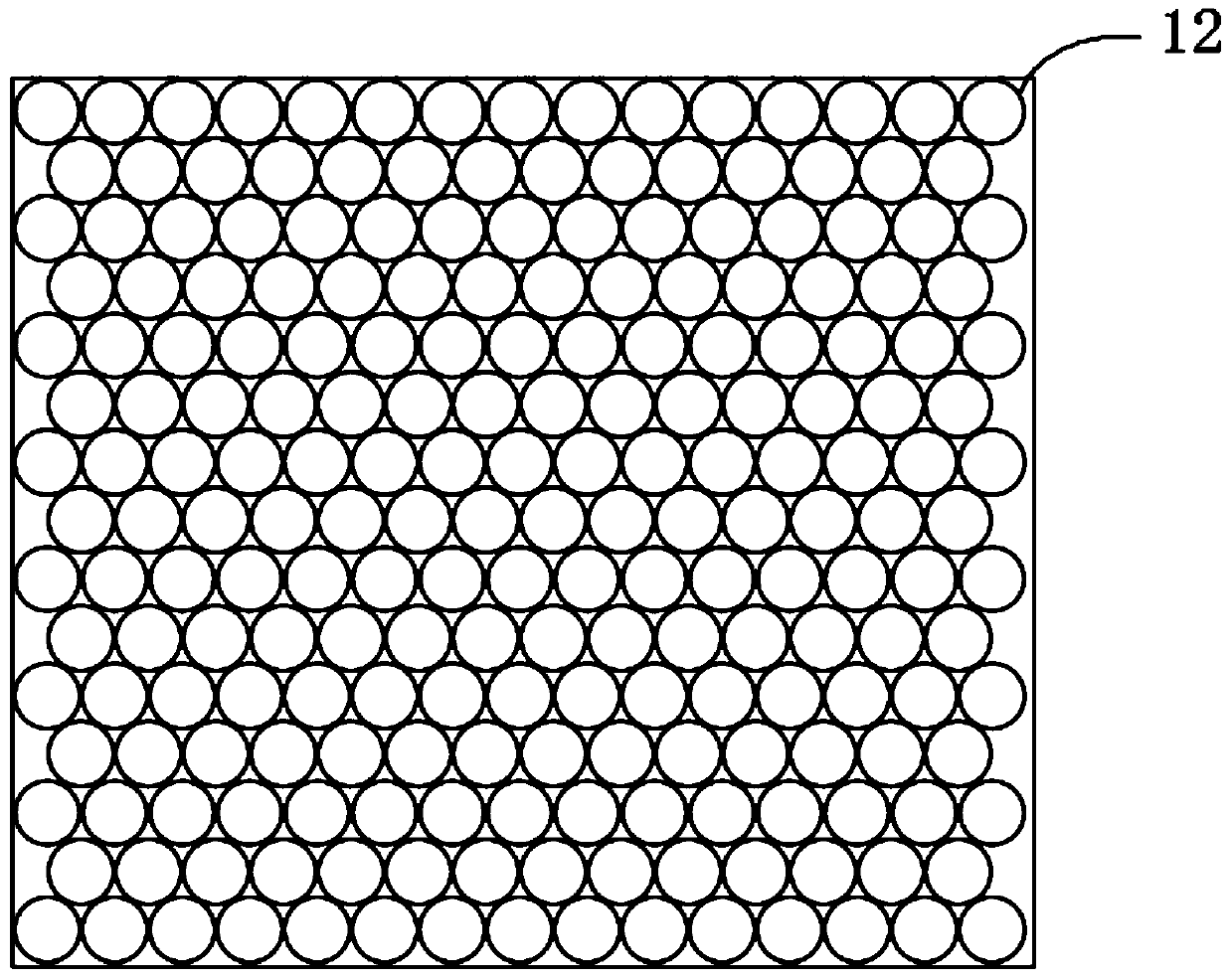
[0041] It should be noted that the cutting line 12 is the infrared laser scribing on the surface of the glass material, so that the glas...

Embodiment 2

[0055] Such as Figure 4 As shown, Embodiment 2 of the present invention provides a glass cutting splinter processing device, which specifically includes the following modules:

[0056] The carrier 20 is used to carry the cover glass to be processed, and realize the five-point positioning of the cover glass at the cutting station;

[0057] The cutting and scribing module 21 is arranged at the front end of the carrier in the conveying direction and above the cover glass, for generating laser light, and cutting and scribing the cover glass according to a set trajectory to obtain a cutting line ;

[0058] The splinter module 22 is arranged at the rear end of the cutting device, and is used to generate laser light, and generate laser thermal stress at the cutting line of the cover glass according to the set trajectory, so that the cut cover glass is under the action of laser thermal stress. lobes.

[0059] Preferably, the cutting tool used when cutting and marking the cover gla...


PUM


Abstract

The invention relates to the technical field of laser processing, and discloses a glass cutting and splitting processing method and device, which are applied to watch glass laser cutting and splitting, and the method comprises the following steps: carrying out five-point positioning on watch cover glass at a cutting station; cutting and scribing the watch cover glass according to a set track to obtain a cutting line; using a transplanting manipulator for transplanting the watch cover glass from the cutting station to a splitting station; and generating laser thermal stress at the watch cover glass cutting line according to the set track so as to split the cut watch cover glass under the action of the laser thermal stress. According to the glass cutting and splitting machining method and device, watch cover glass cutting and splitting machining is integrated into circle cutting machining, only manual feeding and discharging are needed in the production process, the rest of cutting, splitting and carrying are all full-automatic machining, and the labor cost is reduced; compared with a traditional mode that a cutter wheel cuts square blocks and then CNC grinding is conducted to form circles, production efficiency is improved, machining processes are reduced, and the glass product utilization rate is increased.

Description

technical field [0001] The invention relates to the technical field of laser processing, in particular to a glass cutting slivers processing method and device. Background technique [0002] The glass produced by the production process of existing watch glass is a block square glass. In order to cut multiple pieces of circular glass on the glass, the following current solutions are not very ideal: [0003] Mechanical cutting adopts the cutter wheel scribing method. The cutter wheel can only perform square cutting but not circular cutting. After the cutter wheel cuts the square, it needs to be grinded by CNC to grind the square glass into a circle. There are many disadvantages in the mechanical cutting method. For example, the wear of the cutter wheel leads to a decrease in the yield, and it can only process square shapes. It is impossible to process other special-shaped holes, and there are disadvantages such as long time for line change and debugging, and inconvenient daily...

Claims


Application Information

Patent Timeline
Patent Type & Authority Applications(China)
IPC IPC(8): C03B33/04C03B33/02C03B33/09
CPCC03B33/0222C03B33/04C03B33/091Y02P40/57
Inventor 刘祥
Owner 深圳市青虹激光科技有限公司
Learn More