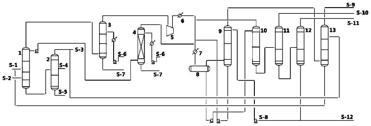
Light hydrocarbon recovery method and device
A light hydrocarbon recovery and absorbent technology, applied in liquid hydrocarbon mixture recovery, chemical instruments and methods, hydrocarbon distillation, etc., can solve the problems of long process, complicated operation, high investment and energy consumption
- Summary
- Abstract
- Description
- Claims
- Application Information
AI Technical Summary
Problems solved by technology
Method used
Image
Examples
Embodiment 1
[0103] Light hydrocarbon recovery unit, including: hot / cold low fraction oil feed pipeline, debutanizer 1, fractionation tower 2, rich gas desulfurization tower 3, liquid hydrocarbon desulfurization tower 4, compressor 5, cooler 6, aftercooler 7. Gas-liquid separation tank 8, absorption tower 9 and separation unit;
[0104] Wherein, the hot / cold low fraction oil feed line is connected with debutanizer 1;
[0105] The debutanizer is equipped with a condenser and a reflux tank, the bottom of the tower is connected to the fractionation tower 2, the top of the tower is connected to the condenser and the reflux tank in turn, the top of the reflux tank is connected to the rich gas desulfurization tower 3, and the bottom of the tank is connected to the liquid hydrocarbon desulfurization tower 4 connections;
[0106] The top of the rich gas desulfurization tower 3 is connected with the compressor 5, the cooler 6, the aftercooler 7, and the gas-liquid separation tank 8 in sequence;
...
Embodiment 2
[0135] use as figure 2 The process flow chart shown is for oil and gas desulfurization and light hydrocarbon recovery.
[0136] Among them, the difference between this embodiment and embodiment 1 is:
[0137] (6) Separation:
[0138] Demethanization: The liquid phase from the bottom of the gas-liquid separation tank 8 removes methane in the demethanizer 10, and at the same time removes a small part of C2 and components above C2, and the gas phase at the top of the demethanizer 10 returns after cooling The gas-liquid separation tank 8, the liquid phase at the bottom of the tower is sent to the deisobutanizer 14; the operating temperature at the top of the demethanizer 10 is 15-40°C, and the operating pressure is 2.25-2.85MPaG;
[0139] Deisobutanization: The liquid phase from the bottom of the demethanizer 10 is separated in the deisobutanizer 14 for components below C3 and C3, and the separated overhead gas phase is sent to the deethanizer 11, and the liquid phase at the bo...
Embodiment 3
[0151] use as image 3 The process flow chart shown is for oil and gas desulfurization and light hydrocarbon recovery.
[0152] Among them, the difference between this embodiment and embodiment 1 is:
[0153] (6) Separation:
[0154] Demethanization: The liquid phase from the bottom of the gas-liquid separation tank 8 removes methane in the demethanizer 10, and at the same time removes a small part of C2 and components above C2, and the gas phase at the top of the demethanizer 10 returns after cooling The gas-liquid separation tank 8, the liquid phase at the bottom of the tower is sent to the depropanizer I12; the operating temperature at the top of the demethanizer 10 is 15-40°C, and the operating pressure is 2.25-2.85MPaG;
[0155] Depropanization: The liquid phase components from the bottom of the demethanizer 10 are separated in the depropanizer I12, and the separated components of C3 and below C3 are extracted from the top of the depropanizer I12 and then sent to the de...
PUM
 Abstract
Description
Claims
Application Information
 - R&D
- Intellectual Property
- Life Sciences
- Materials
- Tech Scout
- Unparalleled Data Quality
- Higher Quality Content
- 60% Fewer Hallucinations
Browse by: Latest US Patents, China's latest patents, Technical Efficacy Thesaurus, Application Domain, Technology Topic, Popular Technical Reports.
© 2025 PatSnap. All rights reserved.Legal|Privacy policy|Modern Slavery Act Transparency Statement|Sitemap|About US| Contact US: help@patsnap.com


