
Detection equipment with powder fluidity characterization device

A technology of testing equipment and fluidity, which is applied in the field of 3D printing, can solve the problems of far difference between measurement results and actual use conditions, differences, large measurement errors, etc., and achieve the effects of easy use and promotion, high measurement accuracy and simple operation

Active Publication Date: 2020-07-10
NINGBO INST OF MATERIALS TECH & ENG CHINESE ACADEMY OF SCI
View PDF15 Cites 3 Cited by
  • Summary
  • Abstract
  • Description
  • Claims
  • Application Information

AI Technical Summary

Problems solved by technology

[0006]1. Observation of microscopic morphology, such as the patent application number 201710316475.5, which discloses a device for testing the fluidity of additive manufacturing powders, including The surface topography measuring device for measuring the surface topography of the powder layer and the density measuring device for measuring the density of the powder layer laid by the powder spreading device. Representative, and the projection method is often used in the measurement, which cannot objectively reflect the actual situation of the object in the 3D space. In addition, there is a big difference between the program and the actual use process, and the guiding significance is not obvious
[0007] 2. Powder flow meter test, because the funnel material used in the test process is very different from the 3D printing powder spreading process, the measurement results are different from the actual use farther away
[0008]3. Angle of repose measurement, due to the light scattering and diffraction of the powder, there is a large gap between the determination of the powder accumulation profile and the ideal situation, so the measurement error is large

Method used


Image

  • Detection equipment with powder fluidity characterization device
  • Detection equipment with powder fluidity characterization device
  • Detection equipment with powder fluidity characterization device

Examples


Embodiment 1

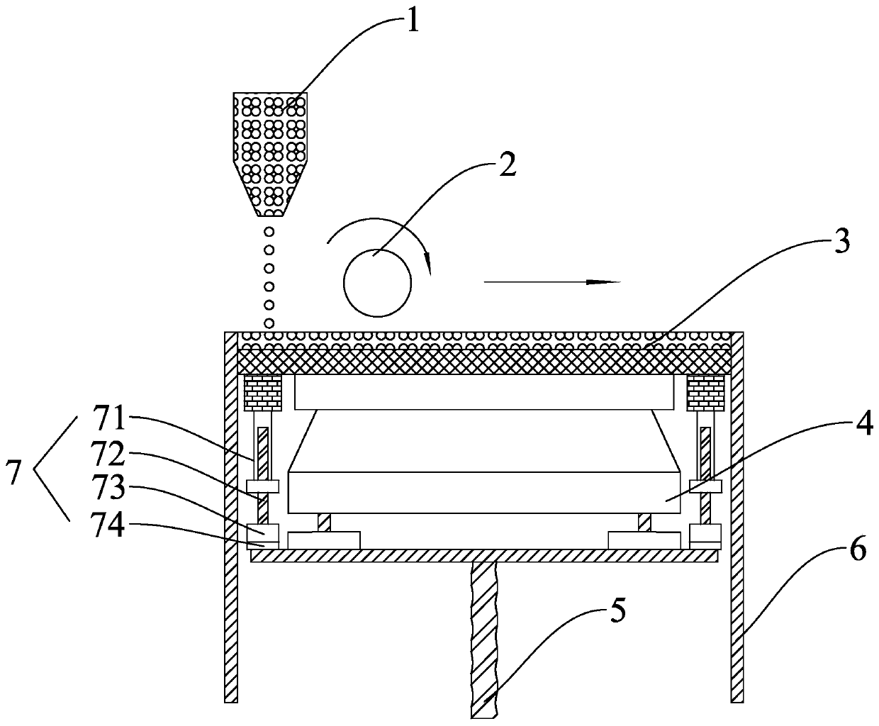
[0046] Such as figure 1 As shown, a detection device with a powder fluidity characterization device includes a powder tank 6, a powder bed 3 that moves up and down along its inner wall is arranged in the powder tank 6, and a powder bed for supplying powder is arranged above the powder bed 3 . The bucket 1 is provided with a valve for opening and closing at the bottom of the funnel 1. The structure of the valve is a prior art, and will not be repeated here.

[0047] A powder scraping mechanism 2 for paving the powder is arranged above the powder bed 3 at the same time. The powder scraping mechanism 2 can be a drum-type structure. The drum-type structure has a moving shaft and a rotating roller rotating around the shaft. This structure is a conventional design. Therefore, it is not shown in detail in the drawings.

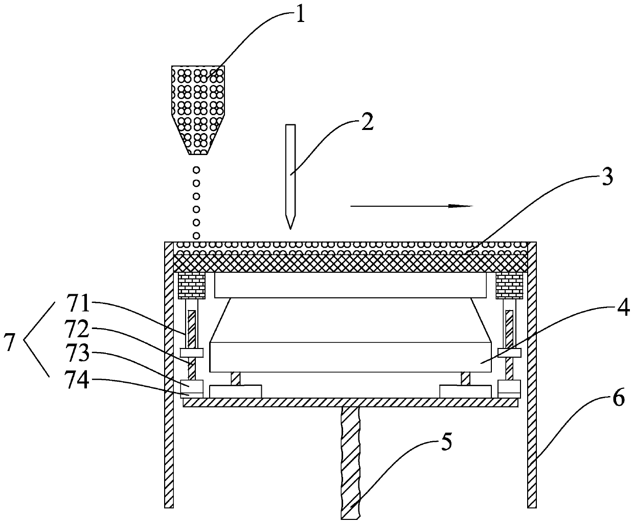
[0048] As another alternative, the above-mentioned powder scraping mechanism 2 can also choose a scraper structure, such as figure 2 As shown, the structure is al...

Embodiment 2

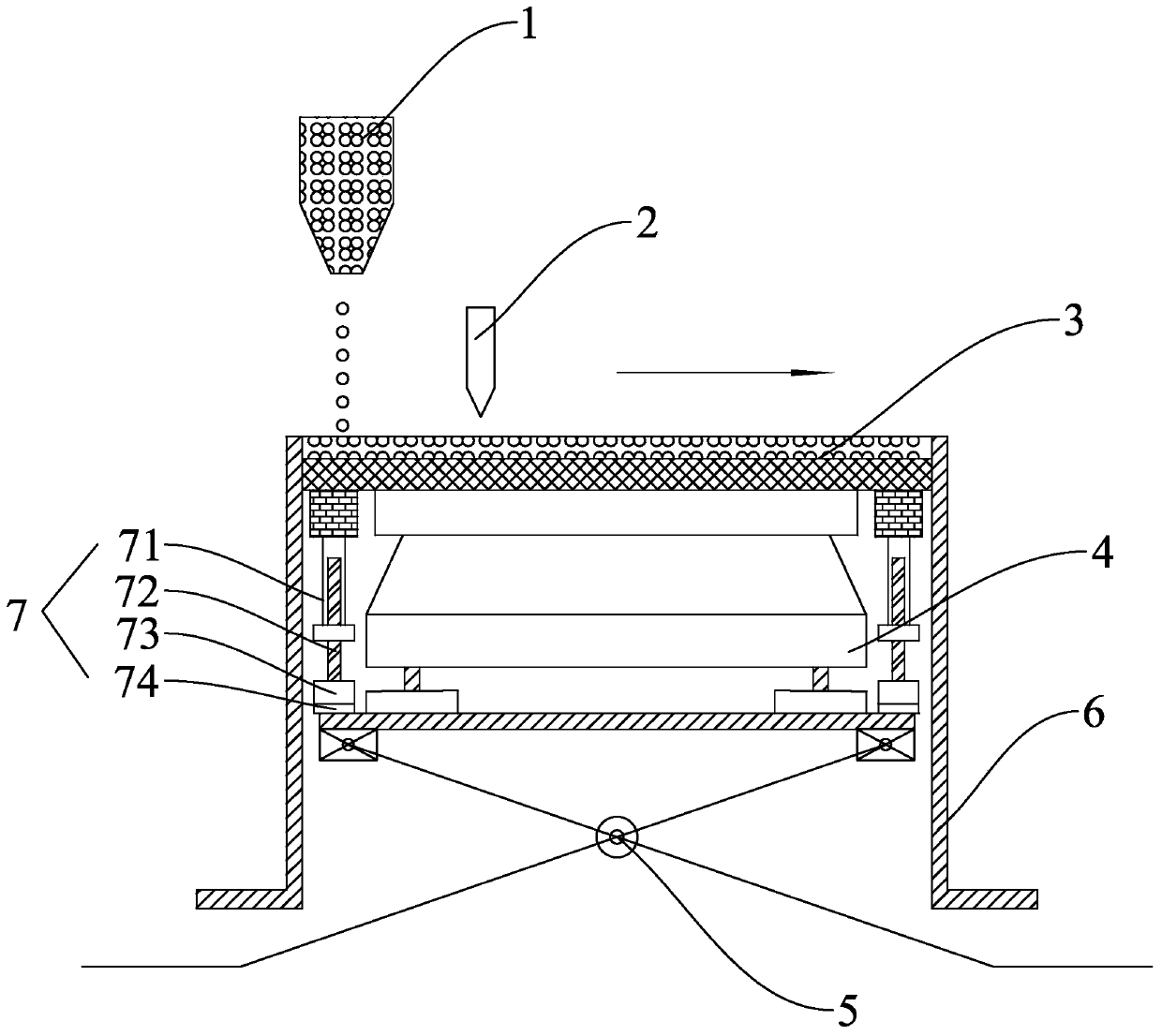
[0057] Such as Figure 4 As shown, the difference between this embodiment and embodiment 1 is that a powder hopper 1 is arranged on both sides above the powder bed 3, so as to increase the supply rate of powder materials.

[0058] Working process of the present invention:

[0059] Start the detection equipment, click the reset button, at this time the powder bed 3 returns to the initial position first, then the powder scraping mechanism 2 returns to the initial position, unlock the locking state of the locking mechanism 7, measure the weight of the powder bed 3 at this time, press Reset operation button, the powder weight is reset;

[0060] Start the locking mechanism 7, slowly lift the powder bed 3 from the mass sensor 4 for a certain distance, and then lock the powder bed 3;

[0061] Start to spread the powder, and the powder material will leak to the powder bed 3 through the valve at the bottom of the hopper 1 under the action of gravity, and then spread the powder on the...


PUM

PropertyMeasurementUnit
densityaaaaaaaaaa
densityaaaaaaaaaa

Abstract

The invention discloses detection equipment with a powder fluidity characterization device. The detection equipment comprises a powder cylinder and a powder bed, and the detection equipment is arranged in the powder cylinder and can move up and down along the inner wall of the powder cylinder; a lifting mechanism which is used for driving the powder bed to move up and down; at least one powder hopper which is arranged above the powder bed; a powder scraping mechanism which is arranged above the powder bed and is used for flattening the powder; the powder fluidity characterization device comprises a mass sensor and a display control device, and the mass sensor is used for measuring the weight of powder laid each time and transmitting data to the display control device; the display control device displays the weight of each time of powder spreading and the weight change between different batches of powder spreading; according to the method, the powder fluidity is quantitatively characterized by combining the theoretical density of the powder material, the test shows that the dynamic process is closer to the actual use process, the test result is more persuasive, and meanwhile, the equipment can accurately characterize the fluidity of different 3D printing powder.

Description

technical field [0001] The invention relates to the technical field of 3D printing, in particular to a detection device with a powder fluidity characterization device. Background technique [0002] Additive manufacturing technology (also known as "3D printing") is a method of directly manufacturing three-dimensional physical entities in a layer-by-layer manner based on a computer-based three-dimensional CAD model. Additive manufacturing technology can quickly and precisely manufacture parts of any complex shape and structure on one piece of equipment, thus realizing "free manufacturing". Compared with traditional processing technology, additive manufacturing can reduce processing costs by more than 20%-40%, and shorten product development cycle by about 80%. In the past 20 years, additive manufacturing technology has developed rapidly, and a variety of molding technologies and equipment have been formed. These technologies are aimed at high-end manufacturing fields such as...

Claims


Application Information

Patent Timeline
Patent Type & Authority Applications(China)
IPC IPC(8): G01N9/36G01N11/00
CPCG01N9/36G01N11/00
Inventor 游良涛李志祥张海青何健雄程昱川段雷许高杰
Owner NINGBO INST OF MATERIALS TECH & ENG CHINESE ACADEMY OF SCI
Learn More