Optical element, method of manufacturing optical element and optical lens

A technology for optical components and optical lenses, which is used in the field of manufacturing optical components, optical lenses, and optical components, and can solve the problems of excessive stray light in optical lenses.

Pending Publication Date: 2020-07-10
ZHEJIANG SUNNY OPTICAL CO LTD
View PDF8 Cites 1 Cited by
  • Summary
  • Abstract
  • Description
  • Claims
  • Application Information

AI Technical Summary

Problems solved by technology

[0005] The main purpose of the present invention is to provide an optical element, a method for manufacturing the optica...

Method used


Image

  • Optical element, method of manufacturing optical element and optical lens
  • Optical element, method of manufacturing optical element and optical lens
  • Optical element, method of manufacturing optical element and optical lens

Examples


Embodiment 1

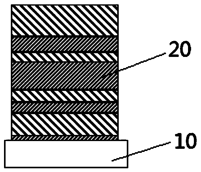
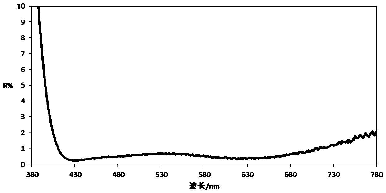
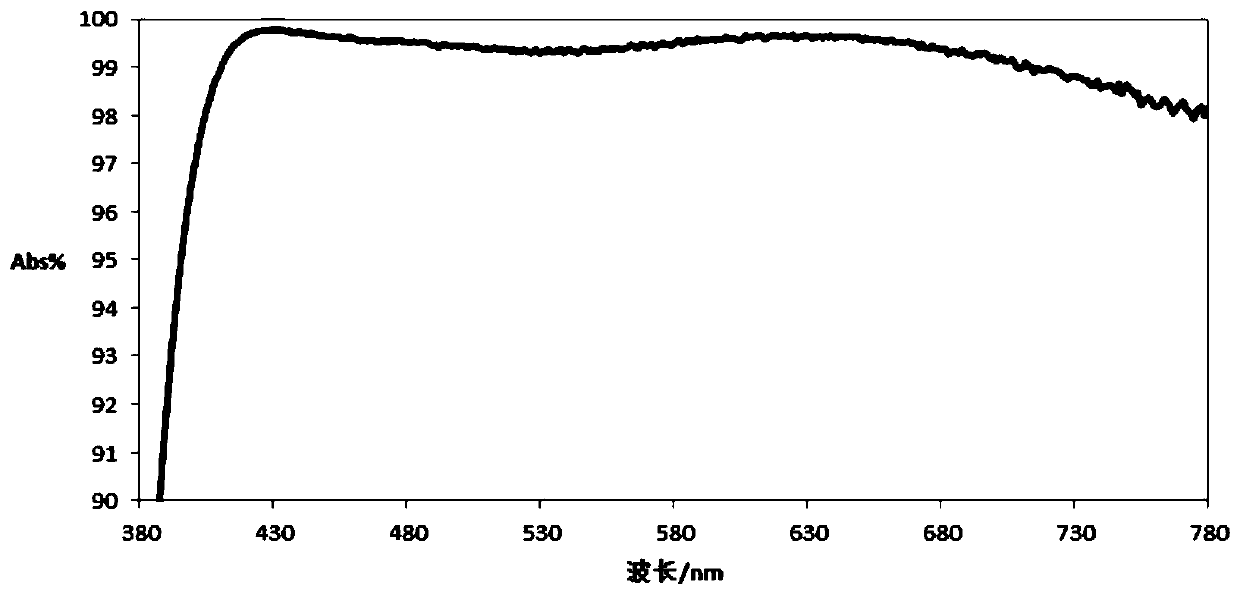
[0041] In this embodiment, when the second film system includes multiple high-refractive-index film layers and multiple low-refractive-index film layers, the high-refractive-index film layers and low-refractive-index film layers are stacked alternately, and the light-absorbing film 20 has a wavelength of 430nm The average reflectance of light in the range of 780nm is R%, R%≦1%; and / or the average absorptivity of the light absorbing film 20 to light in the range of 430nm to 780nm is Abs%, Abs%≧97%. The second film system is alternately stacked high-refractive-index film layers and low-refractive-index film layers, which can effectively increase the light absorption rate, reduce the light reflectance of the main body 10, reduce the generation of stray light, and further improve the imaging quality. By setting a high refractive index film layer and a low refractive index film layer, the average reflectance of the optical element to light can be reduced to less than 1%, and the ave...

Embodiment 2

[0058] The difference from Embodiment 1 is that the structure of the second film system is different.

[0059] In this embodiment, when the second film system has only one film layer, the average reflectance of the light-absorbing film 20 to light with a wavelength in the range of 430nm to 780nm is R%, and R%≦3%; and / or the light-absorbing film 20 The average absorption rate Abs% for light with a wavelength in the range of 430nm to 780nm, Abs%≧97%. When the second film system is only one film layer, it is convenient to manufacture the second film system, and at the same time, it can effectively increase the light absorption rate, reduce the light reflectance of the body 10, reduce the generation of stray light, and improve the imaging quality.

[0060] In this embodiment, the body 10 is glass, the light-absorbing film 20 includes a first film system and a second film system, the second film system is only a metal film layer, and the structure of the film layer of the light-abs...

Embodiment 3

[0062] The difference from Embodiment 1 is that the light absorbing film only has the first film system.

[0063] In this embodiment, the body 10 is glass, and the light-absorbing film 20 only includes the first film system, that is, only includes the metal film layer and the low-refractive index film layer, and its film layer structure is: (Cr / SiO 2 )^4, wherein, the extinction coefficient k of Cr is 2.39, SiO 2 The refractive index of 1.47. Starting from one side of the body 10, the first layer is Cr, and the second layer is SiO 2 , the third layer is Cr, and the fourth layer is SiO 2 .... In this embodiment, the thickness of each film layer in this embodiment is set to be 59.99 nm, 35 nm, 18.31 nm, 33.23 nm, 4.31 nm, 46.55 nm, 9.3 nm, and 5 nm from the side adjacent to the body 10 . In this example SiO 2 As a low refractive index film layer. It should be noted that 4 refers to (Cr / SiO 2 ) repeated four times.


PUM

PropertyMeasurementUnit
Average reflectanceaaaaaaaaaa

Abstract

The invention provides an optical element, a method of manufacturing the optical element and an optical lens. The optical element comprises a body and a light absorption film, at least one part of thebody is plated with the light absorption film. The light absorption film comprises a first film system, wherein the first film system comprises multiple film layers, multiple film layers comprise atleast one metal film layer and at least one low-refractive-index film layer, and when the number of the metal film layers and the number of the low-refractive-index film layers are more than one, themetal film layers and the low-refractive-index film layers are alternately arranged; and a second film system which comprises at least one of a low-refractive-index film layer, a high-refractive-indexfilm layer and a metal film layer, the types of the film layers at the joint of the first film system and the second film system are different, and the first film system or the second film system isconnected with the body. The problem that the optical lens in the prior art has much stray light is solved.

Description

technical field [0001] The invention relates to the technical field of optical imaging equipment, in particular to an optical element, a method for manufacturing the optical element and an optical lens. Background technique [0002] The optical lens is used to image the subject to the imaging surface, such as the optical lens of the mobile phone that is imaged on the sensor, such as a telescope that can observe the image with the naked eye. The lens determines the quality of imaging performance, so the lens performance has become an important consideration in the design of cameras and other equipment. In recent years, with the development of portable electronic devices such as mobile phones, portable electronic devices have higher and higher requirements for lenses. [0003] The optical lens usually includes optical components such as a plastic lens barrel, an optical lens group, a light shield, and a spacer ring. The optical lens group is arranged in the plastic lens barrel...

Claims


Application Information

Patent Timeline
IPC IPC(8): G02B5/00C23C14/24C23C14/20C23C14/10C23C14/08
CPCG02B5/003C23C14/24C23C14/20C23C14/10C23C14/083
Inventor 蒯泽文阮高梁诸烨
Owner ZHEJIANG SUNNY OPTICAL CO LTD
Why Eureka
Try Eureka