Supercharge Your Innovation With Domain-Expert AI Agents!

Light-emitting backlight source of circumferential flat arch combined surface cathode back tip arrow tail gate control structure

A backlight and cathode technology, which is applied in cold cathode manufacturing, discharge tube main electrode, electrode system manufacturing, etc., can solve the problem of low emission efficiency of carbon nanotube cathode, not too many emitted electrons, small carbon nanotube cathode manufacturing area, etc. question

Inactive Publication Date: 2020-07-10
JINLING INST OF TECH
View PDF4 Cites 0 Cited by
  • Summary
  • Abstract
  • Description
  • Claims
  • Application Information

AI Technical Summary

Problems solved by technology

In the carbon nanotube cathode, only a small amount of carbon nanotubes can emit electrons, and the number of emitted electrons is not too much; while most of the carbon nanotubes do not emit electrons, and there are very few carbon nanotubes that emit electrons. The tubes conduct intermittent electron emission, which makes the electron emission efficiency of the overall carbon nanotube cathode very low
This is very unfavorable for improving the technical indicators such as the luminous brightness of the luminous backlight
Second, the control ability of the gate voltage on the carbon nanotube cathode is relatively weak
However, if the gate voltage cannot control the electron emission of the carbon nanotube cathode, or the gate voltage can only weakly control the electron emission of the local carbon nanotube cathode, then the existence of the gate voltage will lose its original function. This is also without any promotional significance for effectively improving the luminous gray scale of the luminous backlight.
Third, the fabrication area of ​​the carbon nanotube cathode is relatively small, and there is not a sufficient number of carbon nanotubes

Method used


Image

  • Light-emitting backlight source of circumferential flat arch combined surface cathode back tip arrow tail gate control structure
  • Light-emitting backlight source of circumferential flat arch combined surface cathode back tip arrow tail gate control structure
  • Light-emitting backlight source of circumferential flat arch combined surface cathode back tip arrow tail gate control structure

Examples


Embodiment Construction

[0049] The present invention will be further described below in conjunction with the accompanying drawings and embodiments, but the present invention is not limited to this embodiment.

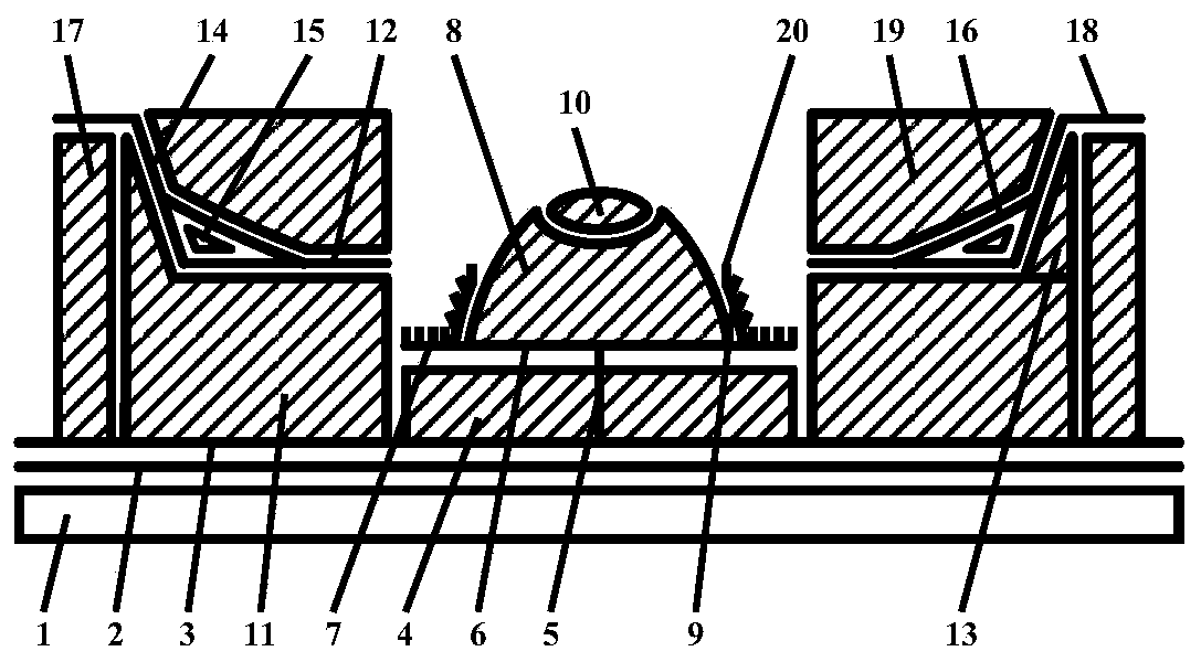
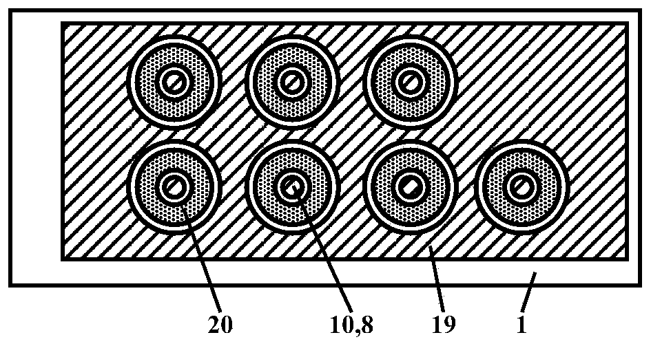
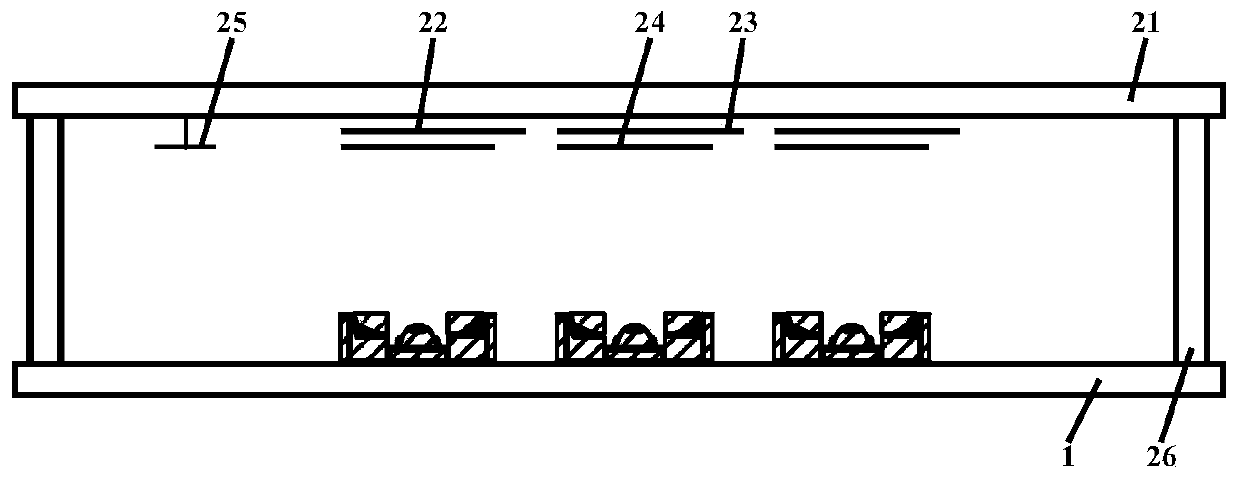
[0050] In this embodiment, the luminescent backlight with the gate-controlled structure of the cathode back point and arrow tail on the surface of the circumferential flat arch joint group is as follows: figure 1 , figure 2 and image 3 As shown, it includes a vacuum enclosure and a getter 25 accessory components located in the vacuum enclosure. The vacuum enclosure is composed of a front hard transparent glass plate 21, a rear hard transparent glass plate 1 and a glass narrow frame strip 26; The transparent glass plate has an anode pad film block layer 22, an anode silver penetrating layer 23 and a thin luminous layer 24. The anode pad film block layer is connected to the anode silver penetrating layer, and the thin luminescent layer is made on On the top of the anode pad film block layer;...


PUM


Abstract

The invention discloses a light-emitting backlight source of a circumferential flat arch combined surface cathode back tip arrow tail gate control structure. The light-emitting backlight source comprises a vacuum sealing body and a getter accessory element positioned in the vacuum sealing body. The vacuum sealing body consists of a front hard transparent glass plate, a rear hard transparent glassplate and a glass narrow frame strip. An anode cushion film block layer, an anode bent silver penetration layer and a thin light-emitting layer are arranged on the front hard transparent glass plate,wherein the anode cushion film block layer is connected with the anode bent silver penetration layer, and the thin light-emitting layer is manufactured on the anode cushion film block layer; and the rear hard transparent glass plate is provided with the circumferential flat arch combined surface cathode back tip arrow tail gate control structure. The light-emitting backlight source has the advantages of being good in light-emitting brightness uniformity and stable in manufacturing process.

Description

technical field [0001] The present invention belongs to the fields of nanometer science and technology, vacuum science and technology, integrated circuit science and technology, plane display technology, semiconductor science and technology, microelectronics science and technology, and optoelectronic science and technology. It relates to the production of planar light-emitting backlight, specifically to the production of planar light-emitting backlight of carbon nanotube cathode, in particular to a kind of light-emitting backlight and its manufacture craft. Background technique [0002] In a suitable vacuum environment, carbon nanotubes can emit electrons, thus constituting an electron source for a certain device or system. Taking advantage of this feature, it can be made into a carbon nanotube cathode, which can be used in a series of vacuum components such as light-emitting backlights. Therefore, the production level of the carbon nanotube cathode can promote the develop...

Claims


Application Information

Patent Timeline
Patent Type & Authority Applications(China)
IPC IPC(8): H01J1/304H01J1/36H01J9/02
CPCH01J1/3044H01J1/3046H01J1/36H01J9/02H01J9/025
Inventor 李玉魁
Owner JINLING INST OF TECH
Features
  • R&D
  • Intellectual Property
  • Life Sciences
  • Materials
  • Tech Scout
  • Unparalleled Data Quality
  • Higher Quality Content
  • 60% Fewer Hallucinations
Learn More