Current control method and system of magnetic levitation planar motor
A planar motor and current control technology, applied in control systems, motor control, AC motor control, etc., can solve the problem of not considering the negative impact of output noise, the difficulty of obtaining the optimal control parameters of the actual system, and the large difference between the simulation model and the actual model and other issues, to achieve the effect of improving robustness and precision, realizing high-precision motion, and wide application range
- Summary
- Abstract
- Description
- Claims
- Application Information
AI Technical Summary
Problems solved by technology
Method used
Image
Examples
Embodiment 1
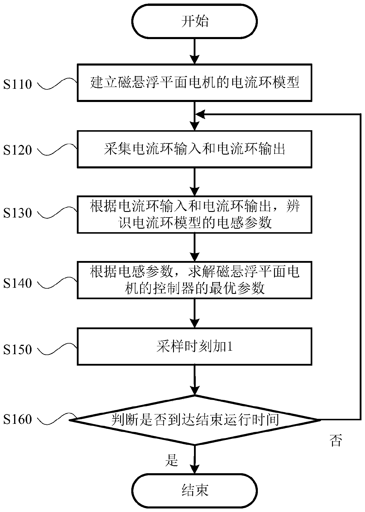
[0070] figure 1 It is a flow chart of the current control method of the magnetic levitation planar motor provided by Embodiment 1 of the present invention. This embodiment is applicable to the high-precision control of the magnetic levitation planar motor, and the method can be executed by the current control system of the magnetic levitation planar motor. The system can be realized by means of software and / or hardware. For example, the system can be a simulation system; or, the system can be configured in a device with a magnetic levitation planar motor, which is usually precision and ultra-precision manufacturing equipment.
[0071] see figure 1 , the current control method of the magnetic levitation planar motor specifically includes the following steps:
[0072] S110, establishing a current loop model of the magnetic levitation planar motor.
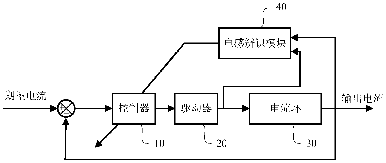
[0073] Wherein, the current loop model may be, for example, a current closed-loop system model. figure 2 A structural block dia...
Embodiment 2
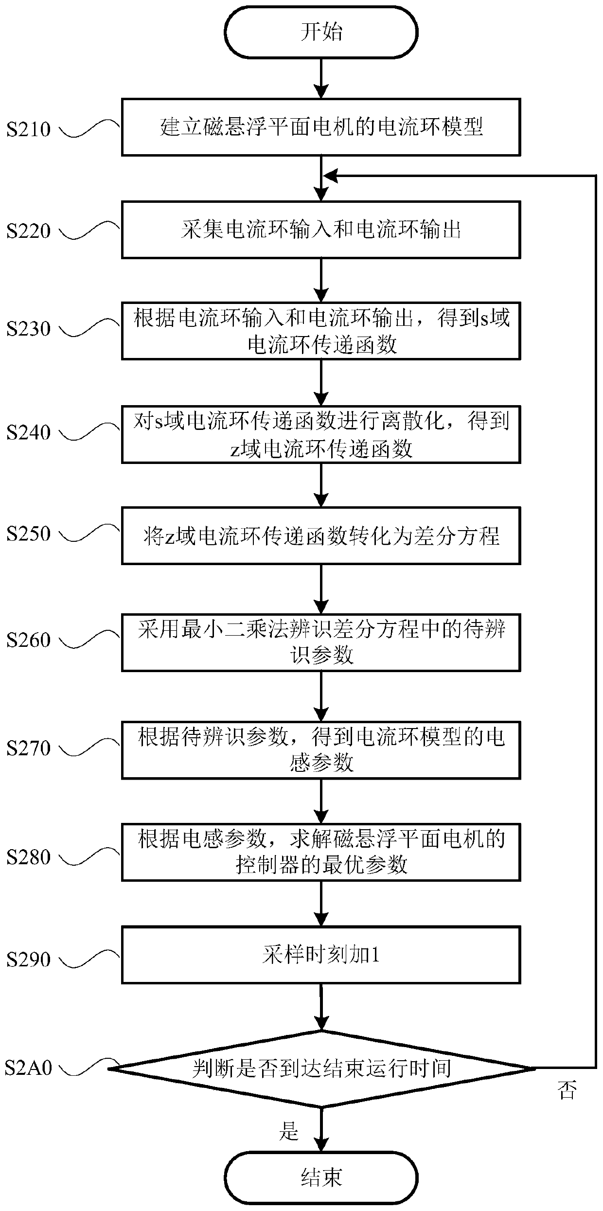
[0101] image 3 It is a schematic flowchart of a current control method for a magnetic levitation planar motor provided in Embodiment 2 of the present invention. see image 3 , on the basis of the first embodiment, the second embodiment refines the method for identifying the inductance parameter of the current loop model in the first embodiment. Optionally, the least square method is used to identify the inductance parameters, which is beneficial to quickly identify the inductance parameters. The current control method specifically includes the following steps:
[0102] S210, establishing a current loop model of the magnetic levitation planar motor.
[0103] S220. Collecting current loop input and current loop output.
[0104] S230. Obtain an s-domain current loop transfer function according to the current loop input and the current loop output.
[0105] Among them, the s-domain current loop transfer function is expressed as the following formula:
[0106]
[0107] In...
Embodiment 3
[0129] Figure 4A structural block diagram of a current loop model provided for Embodiment 3 of the present invention. see Figure 4 , on the basis of the above embodiments, the current loop model further includes a filter 50, which may be, for example, an RC filter. Using the filter 50 can reduce the noise of the current loop 30, therefore, adding the filter 50 to the output terminal of the current loop 30 (ie, the current feedback terminal) can improve the current control accuracy. Exemplarily, the transfer function of the filter 50 is expressed as the following formula:
[0130]
[0131] In the formula, T fliter is the reciprocal of the filter cutoff frequency.
[0132] Optionally, taking the system damping ratio of the current loop model as 0.707 as an example, according to the transfer function of the current loop 30, the transfer function of the driver 20 and the transfer function of the filter 50, the proportional control parameters and the integral control param...
PUM
 Abstract
Description
Claims
Application Information
 - R&D
- Intellectual Property
- Life Sciences
- Materials
- Tech Scout
- Unparalleled Data Quality
- Higher Quality Content
- 60% Fewer Hallucinations
Browse by: Latest US Patents, China's latest patents, Technical Efficacy Thesaurus, Application Domain, Technology Topic, Popular Technical Reports.
© 2025 PatSnap. All rights reserved.Legal|Privacy policy|Modern Slavery Act Transparency Statement|Sitemap|About US| Contact US: help@patsnap.com


