
Glenoid cavity prosthesis and shoulder joint prosthesis applying same

A glenoid and prosthesis technology, applied in the direction of shoulder joints, prostheses, joint implants, etc., can solve the problems of reducing the stability of the glenoid plateau, difficult to replace, wear and tear of the glenoid plateau, and avoid intra-articular hemorrhage risk, ensuring reliability and stability, and reducing the risk of loosening

Pending Publication Date: 2020-07-14
BEIJING CHUNLIZHENGDA MEDICAL INSTR
View PDF0 Cites 0 Cited by
  • Summary
  • Abstract
  • Description
  • Claims
  • Application Information

AI Technical Summary

Problems solved by technology

[0004] However, the glenoid prosthesis in the prior art generally has the following disadvantages: 1) For patients with osteoporosis and poor bone quality, chronic loosening of the glenoid prosthesis often occurs after implantation ; 2) The glenoid plateau of the one-piece glenoid prosthesis is not easy to replace after wear; 3) In order to meet the replacement needs of most patients, the glenoid plateau of the glenoid prosthesis is often designed as a symmetrical structure, As a result, the glenoid plateau cannot fully match the anatomical contour of the patient’s human glenoid, resulting in the glenoid plateau not being able to completely cover the tibial osteotomy plane to achieve the ideal bone coverage area. This will not only reduce the glenoid plateau stability after implantation, thus increasing the risk of long-term glenoid prosthesis loosening, and in long-term use, it will also stimulate the soft tissue around the junction of the glenoid plateau and the osteotomy plane and cause pain, thus increasing the risk of glenoid prosthesis loosening risk of bleeding in joints

Method used


Image

  • Glenoid cavity prosthesis and shoulder joint prosthesis applying same
  • Glenoid cavity prosthesis and shoulder joint prosthesis applying same
  • Glenoid cavity prosthesis and shoulder joint prosthesis applying same

Examples


Embodiment Construction

[0027] In order to better understand the purpose, structure and function of the present invention, a glenoid prosthesis of the present invention will be further described in detail below in conjunction with the accompanying drawings.

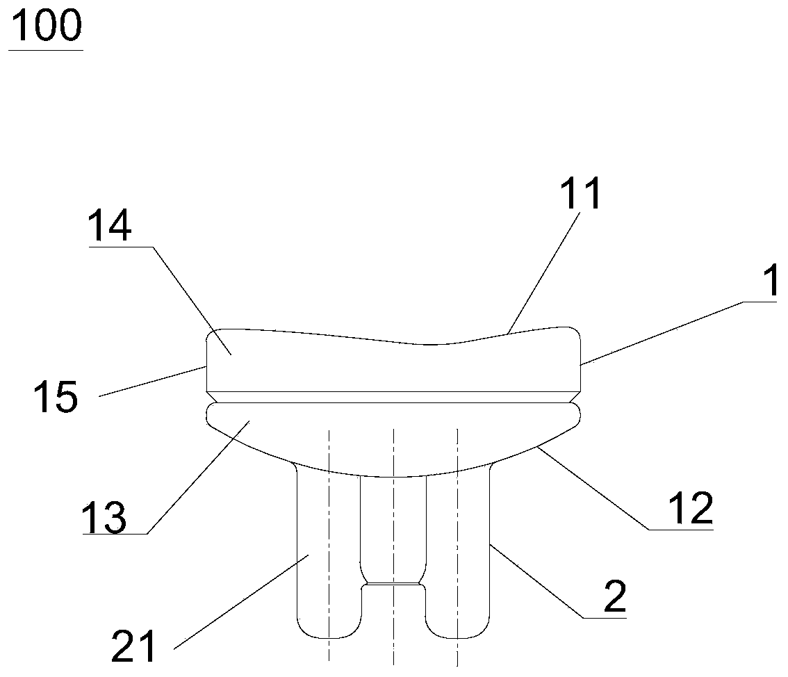
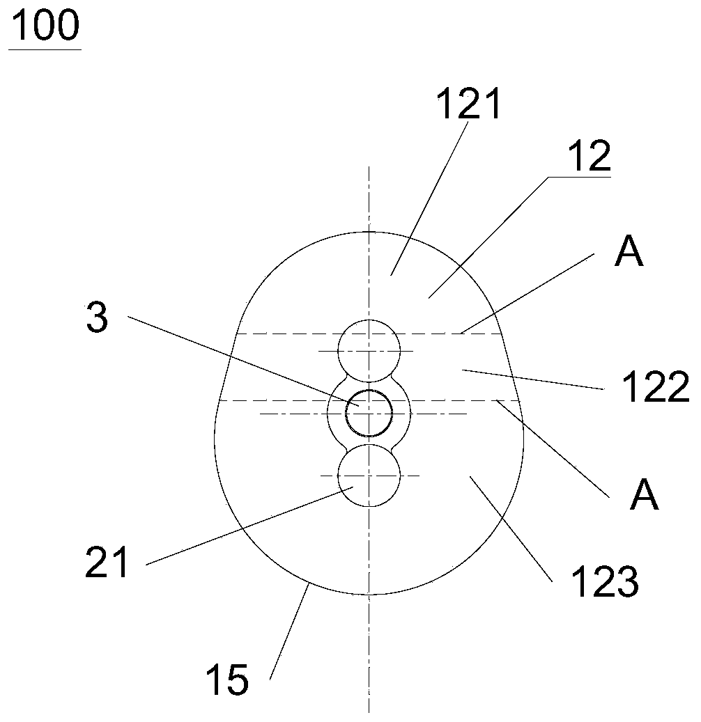
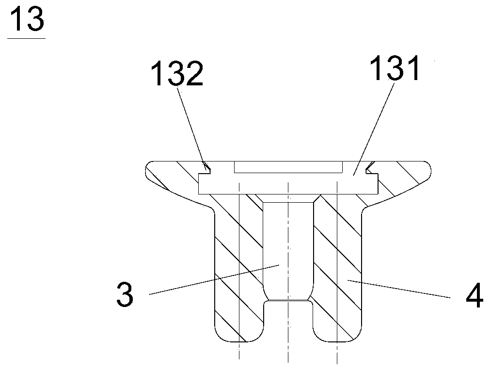
[0028] figure 1 and figure 2 The structure of a glenoid prosthesis 100 according to an embodiment of the present invention is shown. Such as figure 1 and figure 2 As shown, the glenoid prosthesis 100 includes: a prosthesis platform part 1, the prosthesis platform part 1 includes a mating surface 11 for connecting with the humeral head and is opposite to the mating surface 11 and used for interfacing with the osteotomy surface of the human glenoid. Fitted attachment surface 12; and prosthetic medullary rod 2, one end of the prosthetic medullary rod 2 is fixedly connected to the attachment surface 12, and the other end is used to be implanted in the medullary cavity of the human glenoid to be connected to the human glenoid; wherein, The cont...


PUM

PropertyMeasurementUnit
Diameter sizeaaaaaaaaaa
Lengthaaaaaaaaaa

Abstract

The invention belongs to the technical field of medical prosthesis, and discloses a glenoid cavity prosthesis and a shoulder joint prosthesis applying the same. The glenoid cavity prosthesis comprisesa prosthesis platform part and a prosthesis marrow rod, wherein the prosthesis platform part comprises a matching surface which is connected with a humeral head and an adhering surface which is opposite to the matching surface and is used for being attached to the bone section of the glenoid cavity of the human body; one end of the prosthesis marrow rod is fixedly connected with the adhering surface, and the other end of the prosthesis marrow rod is used for being transplanted to the marrow cavity of the glenoid cavity of the human body to be connected with the glenoid cavity of the human body; and the outline structure of the adhering surface is the same as the outline of the bone section of the glenoid cavity of the human body. Through the adoption of the glenoid cavity prosthesis disclosed by the invention, the stability after the prosthesis is transplanted can be effectively improved.

Description

technical field [0001] The invention belongs to the technical field of medical prosthesis, in particular to a glenoid prosthesis and a shoulder joint prosthesis using the same. Background technique [0002] The shoulder joint is the most flexible joint in the body. The main function of the shoulder joint is movement, followed by supporting gravity. The shoulder joint is a typical ball and socket joint, and its movements are divided into flexion, extension, abduction, adduction, external rotation and internal rotation. Shoulder joint replacement surgery is required to treat diseases such as shoulder joint inflammation, humeral head necrosis, tumors, and fractures. Total shoulder prosthesis replacement usually includes a humeral prosthesis and a glenoid prosthesis used in conjunction with the humeral prosthesis. Location. The glenoid prosthesis usually includes a medullary rod for implantation in the human body and a glenoid plateau connected to the medullary rod. The humer...

Claims


Application Information

Patent Timeline
IPC IPC(8): A61F2/40A61F2/30
CPCA61F2/30749A61F2/30767A61F2/40A61F2/4003A61F2002/30028A61F2002/30426A61F2002/30609A61F2002/3093
Inventor 付中国史春宝郭静刘浩
Owner BEIJING CHUNLIZHENGDA MEDICAL INSTR
Learn More