Eureka AIR delivers breakthrough ideas for toughest innovation challenges, trusted by R&D personnel around the world.

Skull traction device used for cervical vertebra dislocation

A traction device and cervical dislocation technology, applied in fractures, non-surgical orthopaedic surgery, medical science and other directions, can solve the problems of excessive traction weight and stretch injury, low reduction rate, long traction time, etc. Conducive to cervical spine creep and reduce manpower loss

Inactive Publication Date: 2020-07-14
HANGZHOU FIRST PEOPLES HOSPITAL
View PDF0 Cites 4 Cited by
  • Summary
  • Abstract
  • Description
  • Claims
  • Application Information

AI Technical Summary

Problems solved by technology

[0006] 1. Jumping weight gain is not conducive to neck muscle relaxation and cervical spine creep. The traction weight may exceed the critical value and cause excessive stretch injury;
[0007] 2. There is no limit to the length of the device, there is a risk of ligament rupture and spinal cord injury
[0008] 3. The angle is fixed, it is difficult to adjust the angle according to the requirements of the traction process
[0009] 4. It needs to be used on a hospital bed with an auxiliary support device, and cannot be used on a hospital bed such as the ICU, operating room, and emergency room, and the use area is limited
[0010] 5. Long traction time and low reset rate

Method used


Image

  • Skull traction device used for cervical vertebra dislocation
  • Skull traction device used for cervical vertebra dislocation
  • Skull traction device used for cervical vertebra dislocation

Examples


Embodiment Construction

[0051] The present invention will be further described below in conjunction with the accompanying drawings.

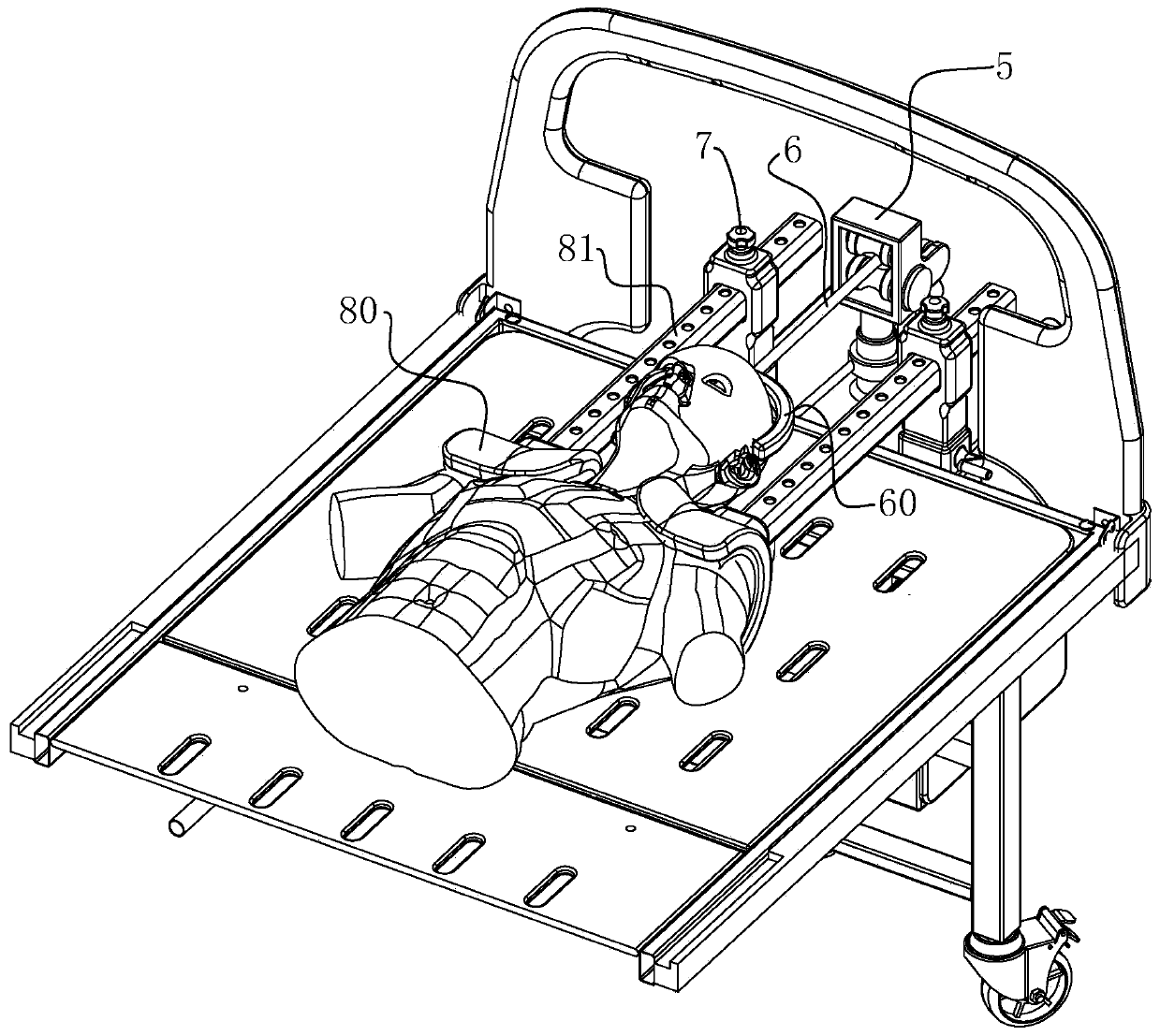
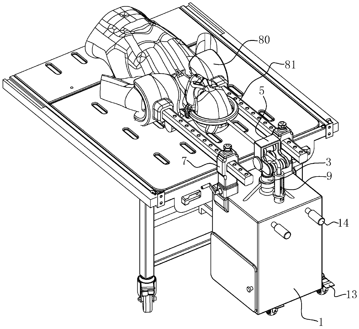
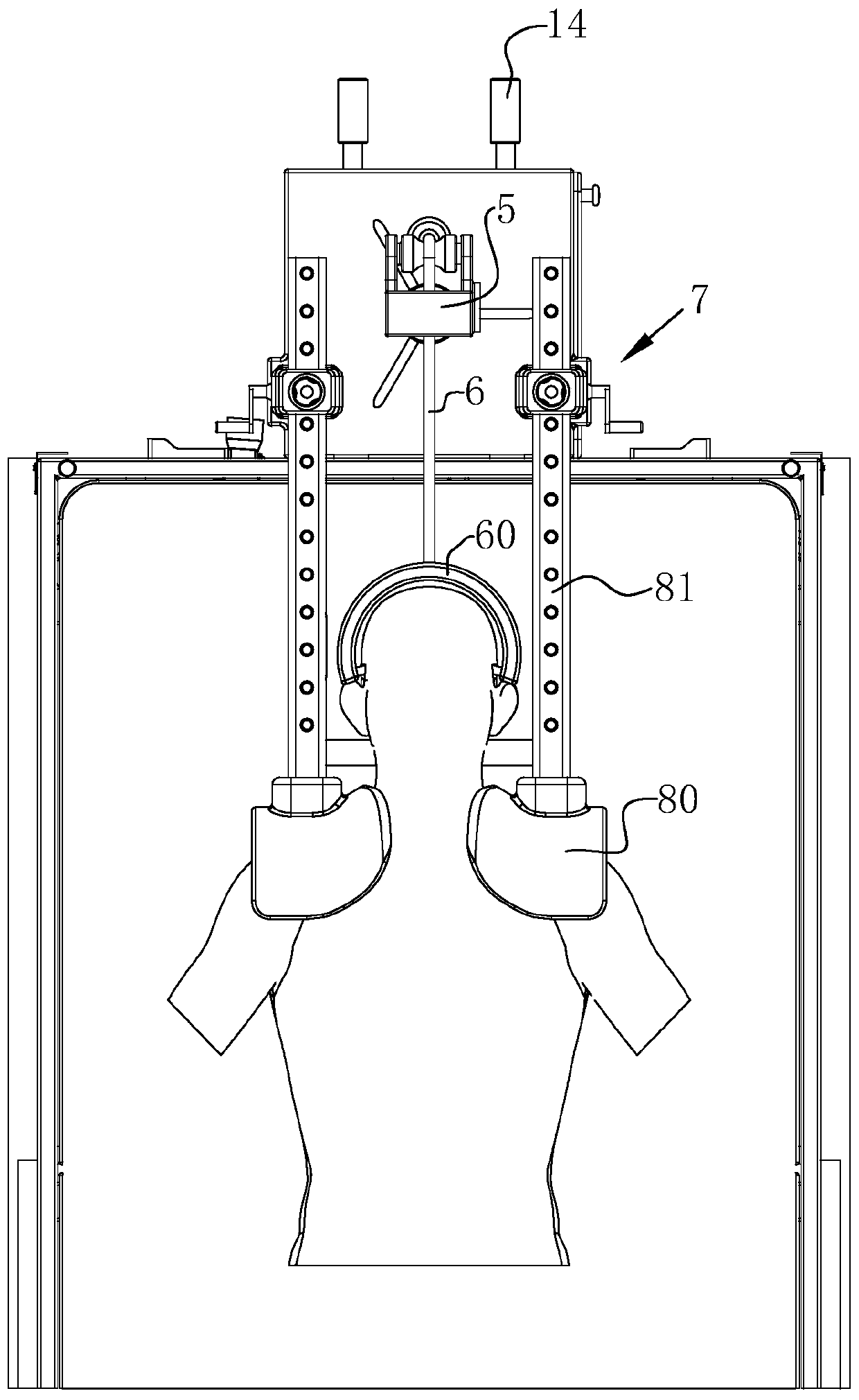
[0052] Such as Figure 7 and Figure 8 The shown skull traction device for cervical dislocation includes a cabinet body 1, the bottom of the cabinet body 1 is provided with a roller 13, and the side of the cabinet body 1 away from the connection assembly 2 is provided with a handle 14; The handle 14 also applies a push-pull force, and the cabinet body 1 drives the roller 13 to roll along the ground, thereby changing the position of the entire traction device. Wherein, the cabinet body 1, as the base of the traction device, can also accommodate related auxiliary equipment.

[0053] Such as figure 2 and Figure 4 As shown, the side of the cabinet body 1 is provided with a connection assembly 2, the connection assembly 2 is used to detachably connect the cabinet body 1 to the hospital bed, the connection assembly 2 includes a rod body fixed on the side wall of the cabin...


PUM


Abstract

The invention discloses a skull traction device used for cervical vertebra dislocation. The skull traction device comprises a cabinet body, wherein one side of the top end of the cabinet body is rotatably provided with connecting components; the connecting components are used for detachably connecting the cabinet body to a hospital bed; the top end of the cabinet body is vertically provided with atelescopic element; the top end of the telescopic element is provided with a guide component used for guiding a traction rope; a traction element is arranged in the cabinet body; the top end of the cabinet body is provided with a through hole; and in addition, the bottom end of the traction rope penetrates through the through hole and is wound to the output end of the traction element. The skulltraction device disclosed by the invention can be flexibly suitable for the height of the hospital bed and is convenient to transport a patient along with the hospital bed, linear transition is increased for traction force, weight can be continuously increased so as to be favorable for muscle relaxation and cervical vertebra creepage and also favorable for restoration, and manpower loss is reduced.

Description

technical field [0001] The invention relates to the technical field of skull traction, in particular to a skull traction device for cervical dislocation. Background technique [0002] Lower cervical dislocation (often referring to the 3rd to 7th cervical vertebrae) is a common cervical spine injury in clinical practice, which often leads to unilateral or bilateral subluxation and total dislocation of the cervical facet joints, and even fractures of the vertebral body, lamina, and spinous process. And often accompanied by different degrees of spinal cord injury, even life-threatening. Therefore, it is very important to quickly restore the vertebral body sequence and the effective volume of the spinal canal, shorten the compression time of the spinal cord, and create favorable conditions for the recovery of nerve function. [0003] Most scholars believe that the most safe, reliable, simple and effective method is to use axial cranial traction reduction. [0004] However, whe...

Claims


Application Information

Patent Timeline
Patent Type & Authority Applications(China)
IPC IPC(8): A61F5/042A61F5/045
CPCA61F5/0104A61F5/042
Inventor 江武朱六龙何帆何齐芳
Owner HANGZHOU FIRST PEOPLES HOSPITAL
Why Eureka
Eureka Blog
Learn More