Machining technology capable of increasing compressive stress depth of surface of rolling wheel

A technology of surface compressive stress and processing technology, used in metal material coating technology, manufacturing tools, coatings, etc., can solve problems affecting the normal operation of common rail oil pumps, unable to meet the performance requirements of rollers, and prone to pitting on the surface of rollers, etc. problems, to avoid surface pitting, improve surface quality, and enhance wear resistance.

Active Publication Date: 2020-07-14
NANJING WEIFU JINNING
View PDF5 Cites 0 Cited by
  • Summary
  • Abstract
  • Description
  • Claims
  • Application Information

AI Technical Summary

Problems solved by technology

[0002] The tappet part is one of the key components in the high-pressure common rail fuel injection pump, and the roller, as the part with the highest working frequency, often has the problem of insufficient surface compressive stress depth after conventional processing, and the surface quality of the roller It directly affects whether the component is qualified or not. Therefore, in the actual work of the common rail pump, once the strength of the roller surface is insufficient, pitting will easily occur, which will affect the normal operation of the common rail oil pump, and may seriously cause damage to the pump.
[0003] At present, the finishing of roller parts is mostly limited to conventional processes such as conventional heat treatment, grinding, rolling and polishing, such as rough turning→heat treatment→rough grinding of the outer circle→grinding both ends→fine grinding of the outer circle→grinding the center hole, etc. After this Although the rollers can be guaranteed to achieve sufficient dimensional accuracy and high roughness after processing, and the surface compressive stress can reach -500Mpa, the depth of compressive stress is too shallow to meet the long-term high-stress working state or in different media. Performance requirements of working rollers

Method used


Image

  • Machining technology capable of increasing compressive stress depth of surface of rolling wheel
  • Machining technology capable of increasing compressive stress depth of surface of rolling wheel
  • Machining technology capable of increasing compressive stress depth of surface of rolling wheel

Examples


Embodiment Construction

[0020] Embodiments of the present invention will be disclosed in the following diagrams. For the sake of clarity, many practical details will be described together in the following description. It should be understood, however, that these practical details should not be used to limit the invention. That is, in some embodiments of the invention, these practical details are not necessary. In addition, for the sake of simplifying the drawings, some well-known and commonly used structures and components will be shown in a simple schematic manner in the drawings.

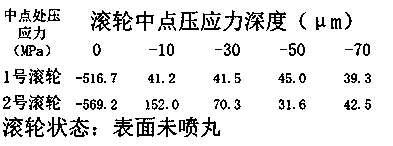
[0021] Taking the current production and processing CB18 roller as an example, the processing technology to increase the depth of compressive stress on the surface of the roller includes the following steps:

[0022] Step 1. Rough turning: Rough turning is performed on the blank, and the basic shape is processed;

[0023] Step 2. Heat treatment: Carburizing and quenching, cold treatment, tempering and aging treatment a...


PUM

PropertyMeasurementUnit
hardnessaaaaaaaaaa
depthaaaaaaaaaa

Abstract

The invention relates to a processing technology capable of increasing compressive stress depth of the surface of a rolling wheel. The machining technology comprises the following steps of rough turning, heat treatment, excircle rough grinding, shot blasting, and two-end-face grinding, wherein fine grinding on an excircle and a middle hole is conducted by using a double-disc grinder to machine theexcircle and the middle hole into the size of a finished product in the two-end-face grinding step. Compared with a conventional machining technology of the rolling wheel, a shot-throwing process isadded after rough grinding on the excircle is conducted, steel shots with a diameter of 0.5mm are used to continuously impacts the surface of the rolling wheel in a shot blasting machine to greatly enhance the surface compressive stress of the rolling wheel, a compressive stress hardened layer with sufficient depth is obtained, meanwhile, too many hardened layers cannot be consumed in subsequent machining, and the abrasion resistance of the rolling wheel is greatly enhanced.

Description

technical field [0001] The invention belongs to the technical field of roller machining, and in particular relates to a process method for increasing the depth of compressive stress on the surface of a roller. Background technique [0002] The tappet part is one of the key components in the high-pressure common rail fuel injection pump, and the roller, as the part with the highest working frequency, often has the problem of insufficient surface compressive stress depth after conventional processing, and the surface quality of the roller It directly affects whether the component is qualified or not. Therefore, in the actual work of the common rail pump, once the strength of the roller surface is insufficient, pitting is easy to occur, which affects the normal operation of the common rail oil pump, and may seriously cause damage to the pump. [0003] At present, the finishing of roller parts is mostly limited to conventional processes such as conventional heat treatment, grind...

Claims


Application Information

Patent Timeline
Patent Type & Authority Applications(China)
IPC IPC(8): C21D1/18C21D7/06C21D1/06C21D9/34C23C8/22
CPCC21D1/18C21D7/06C21D1/06C21D9/34C23C8/22C21D2261/00
Inventor 刘满飞张天意
Owner NANJING WEIFU JINNING
Why Eureka
Try Eureka