Electronic valve and valve body structure thereof

A technology of electronic valve and valve body, which is applied in the direction of valve shell structure, valve details, valve device, etc., can solve the problems of increasing the number of parts and manufacturing cost, high manufacturing cost, high cost of mold and parts, and reduce the number of parts , Reduce the number of molds, and the size is easy to guarantee

Pending Publication Date: 2020-07-14
ZHEJIANG YINLUN MACHINERY
View PDF0 Cites 1 Cited by
  • Summary
  • Abstract
  • Description
  • Claims
  • Application Information

AI Technical Summary

Problems solved by technology

[0006] 1. The upper part of the valve body and the lower part of the valve body are assembled into components, and it is difficult to ensure a high coaxiality between the valve core shaft and the output gear shaft. If the coaxiality accuracy cannot be guaranteed during assembly, the efficiency of power transmission will be reduced, and it may also cause rotation The stuck, making the electronic valve invalid
[0007] 2. The electronic valve structure assembled on the upper part of the valve body and the lower part of the valve body needs to set up molds for the upper part of the valve body, the lower part of the valve body and the connecting bracket in the middle, and the mold cost and parts cost are relatively high
[0008] 3. When assembling the upper part of the valve body and the lower part of the valve body, it is necessary to fix the bracket 7' and the lower part of the valve body 5' through a set of screws, and then connect the connecting column 8' of the bracket to the upper part of the valve body 6' through another set of screws 2' for fixing, so the number of parts is large, the assembly is complicated, and the manufacturing cost is high
[0009] 4. When multiple parts are combined, the contact parts are likely to cause poor sealing
Adjacent parts need to be sealed by sealing rings, which in turn increases the number of parts and manufacturing costs of the product

Method used


Image

  • Electronic valve and valve body structure thereof
  • Electronic valve and valve body structure thereof
  • Electronic valve and valve body structure thereof

Examples


Embodiment Construction

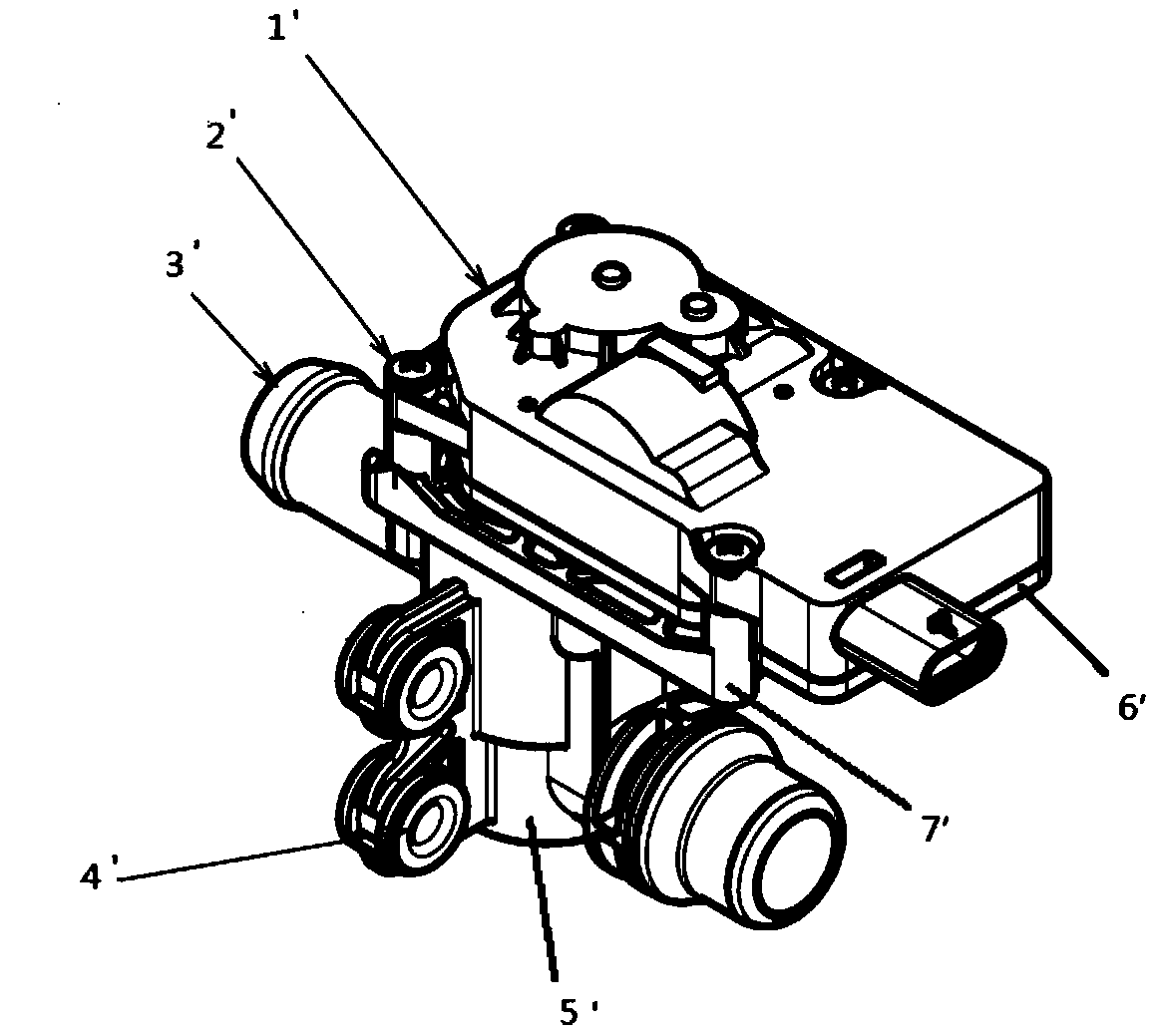
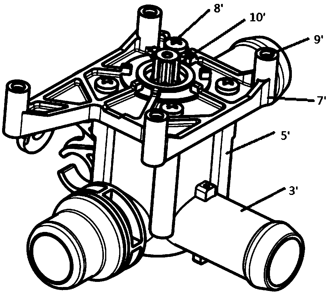
[0042] figure 2 with image 3 It is a structural schematic diagram of an existing electronic valve, and its defects have been described above, and will not be repeated here.

[0043] In the description of the present invention, the directions or positions indicated by "up", "down", "left", "right", "top", "bottom" etc. are based on the directions or positional relationships shown in the drawings, and are only for the purpose of It is convenient to describe the present invention and simplify the description, but does not indicate or imply that the device or element referred to must have a specific orientation, be constructed and operate in a specific orientation, and thus should not be construed as limiting the present invention.

[0044] refer to Figure 4 , an electronic valve of the present invention includes a valve body assembly 2 , a flow control device 1 and a power device 3 .

[0045] The valve body assembly 2 includes a valve body, the valve body includes a valve b...


PUM


Abstract

The invention discloses an electronic valve. The electronic valve includes a valve body assembly, a flow control device and a power device. The valve body assembly includes a valve body, the valve body includes a valve body upper part and a valve body lower part, an upper end cover is arranged on the valve body upper part, and a connecting pipe and a lower end cover are arranged on the valve bodylower part; the power device is arranged in a space formed by the upper end cover and the valve body upper part; and the flow control device is arranged in a space formed by the lower end cover and the valve body lower part. The electronic valve is characterized in that the valve body upper part and the valve body lower part are integrally molded by injection molding. According to the electronic valve, the structure design is reasonable; the valve body is integrally molded in an mold opening mode, the number of parts is reduced, the assembly processes of the valve body upper part and valve body lower part are reduced, and the number of open molds of product parts is reduced, and the development cycle and research and development cost are recued; and moreover, the size of the products is easy to ensure, the weight can further be reduced, and the lightweight and integrated purposes required by a main engine plant are easier to achieve.

Description

technical field [0001] The invention relates to the technical field of new energy vehicles, in particular to the field of electronic valve products used in thermal management systems of new energy vehicles, in particular to an electronic valve and its valve body structure in the vehicle water system. Background technique [0002] Pure electric vehicles and hybrid vehicles use batteries as the power source, and the performance and quality of these vehicles depend to a large extent on the performance of the power battery packs they are equipped with. Therefore, battery thermal management must be carried out on the power battery to keep its working temperature in a better range. [0003] figure 1 Shown is the schematic diagram of the current new energy battery liquid cooling and heating system. Automotive air conditioners consist of compressors, condensers, expansion valves and evaporators, forming a refrigerant circuit. Since new energy vehicles require thermal management o...

Claims


Application Information

Patent Timeline
Patent Type & Authority Applications(China)
IPC IPC(8): F16K27/06F16K41/06
CPCF16K27/065F16K41/066
Inventor 马俊
Owner ZHEJIANG YINLUN MACHINERY
Why Eureka
Try Eureka