Novel laser scanning projection method

A laser scanning and projection technology, applied in the direction of using optical devices, image data processing, measuring devices, etc., can solve the problems of long operation time, reduce assembly efficiency, position deviation of projection graphics, etc., and achieve the effect of real-time correction

Active Publication Date: 2020-07-14
中山荔威光电科技有限公司
View PDF7 Cites 11 Cited by
  • Summary
  • Abstract
  • Description
  • Claims
  • Application Information

AI Technical Summary

Problems solved by technology

The operation of establishing and solving the coordinate transformation relationship takes a long time, the operation is complicated, and the assembly efficiency and product quality are reduced.
[0005] The more serious problem is that at the manufacturing and assembly site, the projected target object will inevitably change its position and attitude. The change of position and attitude will lead to deviations in the position of the projected graphics, and it is impossible to achieve accurate projection graphics based on laser scanning. Operations such as parts installation and positioning

Method used


Image

  • Novel laser scanning projection method
  • Novel laser scanning projection method
  • Novel laser scanning projection method

Examples


Embodiment 1

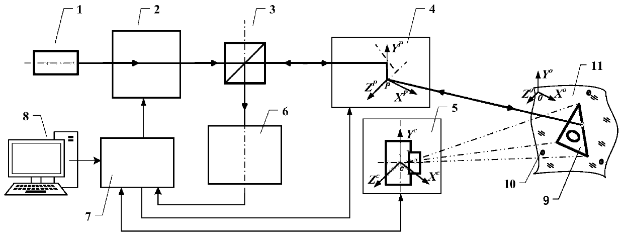
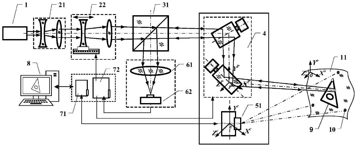
[0079] like image 3 As shown, a novel laser scanning projection device includes: a laser 1, a laser beam expander collimation module 21, an autofocus module 22, a beam splitting prism 31, a two-axis scanning galvanometer module 4, a monocular photogrammetry camera 51, and a light intensity Feedback focusing lens 61, avalanche photodiode detector 62, image acquisition and control board 71, data acquisition and control board 72, host computer controller 8, laser scanning projection graphics 9, back reflection cooperation target 10, projected target Object 11.

[0080] The laser beam emitted by the laser 1 enters the laser beam expansion and collimation module 21 arranged in front of its optical path to complete the collimation and beam expansion of the laser beam, so as to reduce the divergence angle of the laser beam as much as possible. Then it is incident to the auto-focus module 22 arranged in front of the optical path of the laser beam expander and collimator module 21, w...


PUM


Abstract

The invention discloses a novel laser scanning projection method. The method comprises the following steps: automatically calculating and calibrating a coordinate conversion relationship between a double-axis scanning galvanometer coordinate system and a projected target object coordinate system; converting a relation according to the derived coordinate system; calculating the rotation angle of the circle center of each back reflection cooperation target relative to a biaxial scanning galvanometer coordinate system; automatically controlling the light beam to complete optical scanning of eachback reflection cooperative target via the biaxial scanning galvanometer module; according to the position and attitude information of the projected target object, re-calculating the coordinate transformation relationship; realizing real-time automatic detection of the position and posture of the projected target object via real-time correction of the position deviation of the projection graph isrealized;; reading the CAD mathematical model of the to-be-projected part via the upper computer controller and driving the double-axis scanning galvanometer module to rotate circularly through the data acquisition processing and control module, and forming a contour line frame graph of the to-be-assembled part on the projected target object.

Description

technical field [0001] The invention belongs to the field of advanced photoelectric testing instruments, and in particular relates to a novel laser scanning projection method, which is specifically applied to intelligent auxiliary assembly positioning in the field of advanced manufacturing and assembly. Background technique [0002] The laser scanning projector is mainly used in the field of advanced intelligent manufacturing assembly. The instrument can drive the two-axis scanning galvanometer for high-precision deflection according to the three-dimensional CAD digital model of the parts to be processed or assembled, so that the light emitted by the laser is quickly deflected, thereby At the target projection position in the three-dimensional space, the contour line frame of the part outline formed by the rapid circular scanning of the laser light is displayed. The laser outline frame is bright, clearly visible, and can accurately display the three-dimensional position of t...

Claims


Application Information

Patent Timeline
Patent Type & Authority Applications(China)
IPC IPC(8): G01B11/00G01B11/24G06T3/60
CPCG01B11/002G01B11/2433G06T3/604
Inventor 侯茂盛刘涛陈雨情李丽娟林雪竹刘智超郭丽丽
Owner 中山荔威光电科技有限公司
Why Eureka
Try Eureka