Submersible permanent magnet motor unit rotor with combined punching sheets

A technology of unit rotor and permanent magnet motor, which is applied in the direction of electrical components, manufacturing motor generators, magnetic circuit rotating parts, etc., can solve the problems of permanent magnet fragmentation, collision, and large eddy current loss of permanent magnets, etc., and achieve shortened length, The effect of low flux leakage and high power density

Pending Publication Date: 2020-07-14
SHENYANG POLYTECHNIC UNIV
View PDF6 Cites 0 Cited by
  • Summary
  • Abstract
  • Description
  • Claims
  • Application Information

AI Technical Summary

Problems solved by technology

[0003] In order to solve the problem of high difficulty in manufacturing the rotor of the submersible motor and the low utilization coefficient of the permanent magnet, the rotor in the patent (application number 201010253462.6, application number 201310739094.X) adopts a permanent magnet surface-mounted structure, while the slender structure of the submersible motor will The fragile permanent magnets are easily collided with the inside of the stator during assembly and operation, causing the permanent magnets to break
The rotors in the patent (application number 201821173356.5, application number 201820920875.7, application number 201721097916.9) adopt a built-in permanent magnet structure, which solves the defect that the permanent magnet is fragile in the above patent, but in order to ensure the mechanical strength, the built-in rotor adopts a wider The magnetic isolation bridge leads to the defect of more magnetic flux leakage in the rotor
The patent (application number 201820920875.7) adopts the design scheme that each pole corresponds to a permanent magnet. Due to the small number of motor poles, there are defects of large eddy current loss of the permanent magnet and low utilization of the rotor space.
In the patent (application number 201320121619.9), the rotor adopts the scheme of 45# steel slotting, which has the defects of low magnetic permeability and large eddy current loss

Method used


Image

  • Submersible permanent magnet motor unit rotor with combined punching sheets
  • Submersible permanent magnet motor unit rotor with combined punching sheets
  • Submersible permanent magnet motor unit rotor with combined punching sheets

Examples


Embodiment Construction

[0050] Below in conjunction with accompanying drawing, the present invention will be further described:

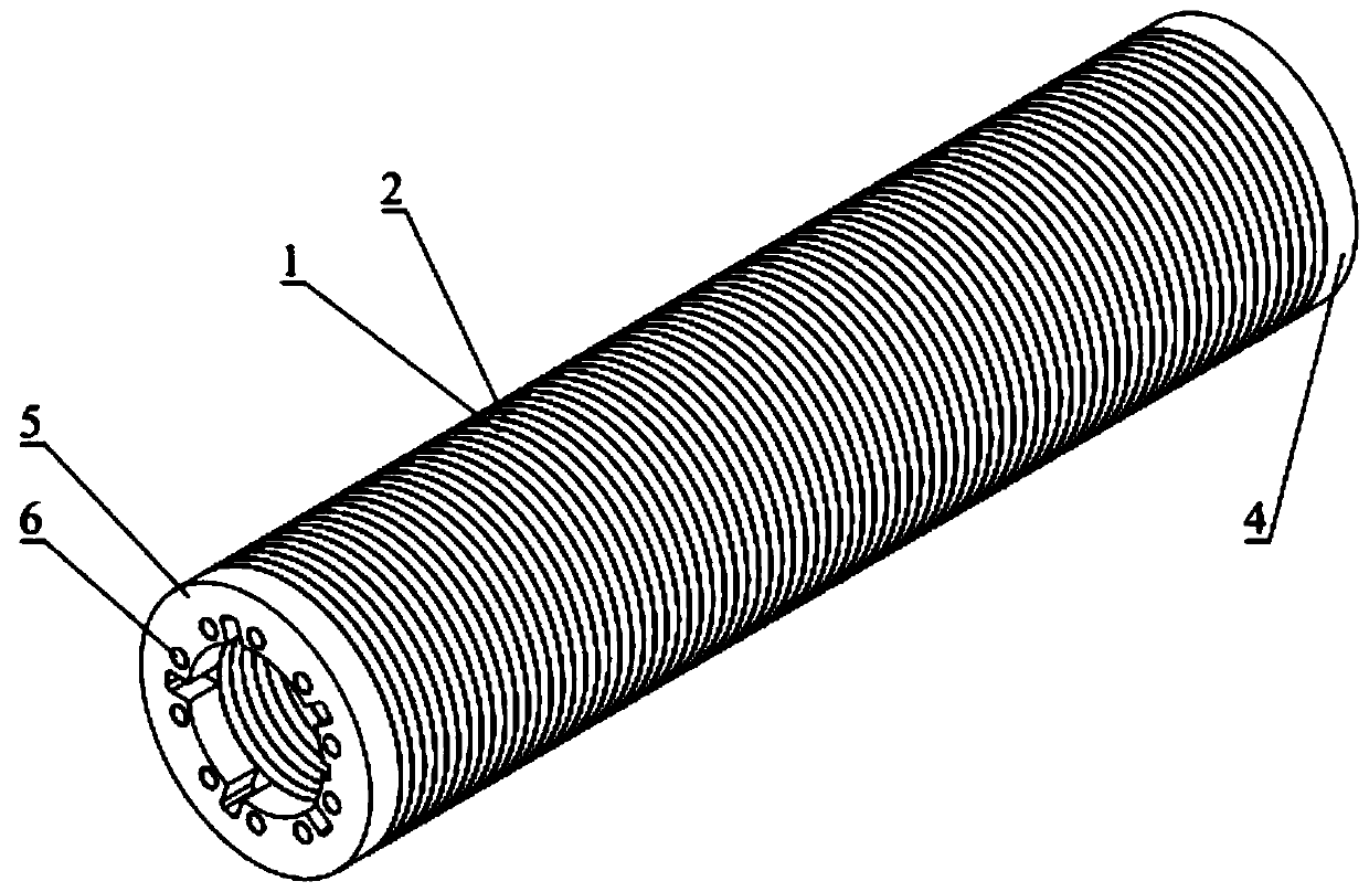
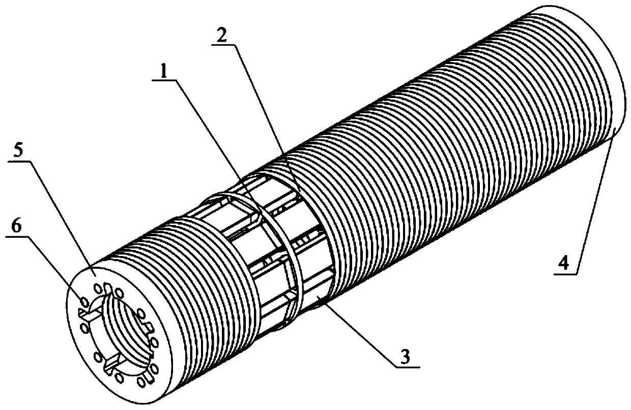
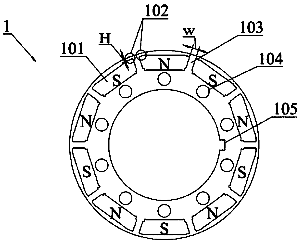
[0051] A unit rotor of combined stamping submersible permanent magnet motor, the unit rotor includes a high-strength iron core punch 1, a low-leakage magnetic core punch 2, a permanent magnet 3, an end plate A4, an end plate B5 and a locking rod 6;

[0052] The high-strength iron core punch 1 and the low-leakage magnetic core punch 2 are stacked alternately (that is, alternately arranged in an array, that is, a high-strength iron core punch 1 is pressed together next to a low-leakage magnetic core punch 2), Place the permanent magnet 3 in the permanent magnet groove 101 of the high-strength iron core punch 1 and the low-leakage magnet core punch 2,

[0053] Place the end plate A4 and the end plate B5 on both sides of the structure formed by laminating the high-strength iron core punch 1 and the low-leakage magnetic core punch 2, and place the high-strength iron core punch ...


PUM


Abstract

The utility model discloses a submersible permanent magnet motor unit rotor with combined punching sheets. The unit rotor comprises high-strength iron core punching sheets, low-leakage magnetic core punching sheets, permanent magnets, an end plate A, an end plate B and a locking rod, the high-strength iron core punching sheets and the low-leakage magnetic iron core punching sheets are arranged inan alternate and laminated mode. Permanent magnets are placed in the permanent magnet grooves of the high-strength iron core punching sheet and the low-leakage magnetic core punching sheet; an end plate A and an end plate B are placed on two sides of a structure formed by alternately laminating the high-strength iron core punching sheets and the low-leakage magnetic core punching sheets; the high-strength iron core punching sheet, the low-leakage magnetic iron core punching sheet, the end plate A and the end plate B are fastened together to form a unit rotor. Compared with a traditional submersible motor unit rotor, the motor has the advantages of being low in magnetic flux leakage and high in power density; under the constraint condition of the same outer diameter and power, the length isshortened by about 20%, and the downhole operation of an electric submersible pump unit (provided with the motor) is facilitated.

Description

technical field [0001] The invention relates to a permanent magnet motor rotor, in particular to a rotor structure of an oil submersible permanent magnet synchronous motor. Background technique [0002] The submersible permanent magnet motor greatly improves the efficiency of the submersible electric pump, especially the direct drive submersible motor cancels the reducer, which improves the reliability of the system, making the submersible permanent magnet motor popular in the field of oil production. The slender structure of the motor brings the problems of high difficulty in manufacturing the rotor and low utilization factor of the permanent magnets. [0003] In order to solve the problem of high difficulty in manufacturing the rotor of the submersible motor and the low utilization coefficient of the permanent magnet, the rotor in the patent (application number 201010253462.6, application number 201310739094.X) adopts a permanent magnet surface-mounted structure, while the...

Claims


Application Information

Patent Timeline
Patent Type & Authority Applications(China)
IPC IPC(8): H02K1/27H02K15/03
CPCH02K1/2766H02K15/03H02K2213/03
Inventor 董婷黄居言彭兵陆万峰张俊
Owner SHENYANG POLYTECHNIC UNIV
Why Eureka
Try Eureka