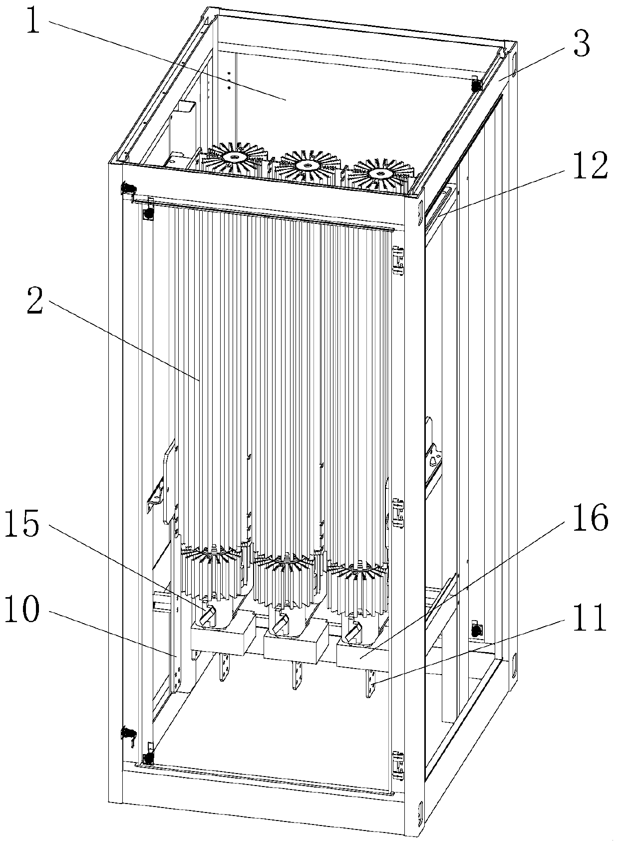
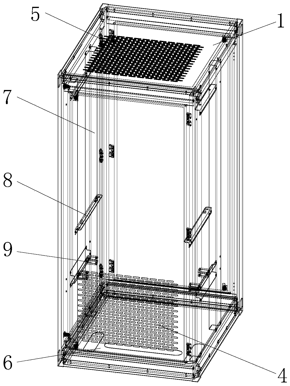
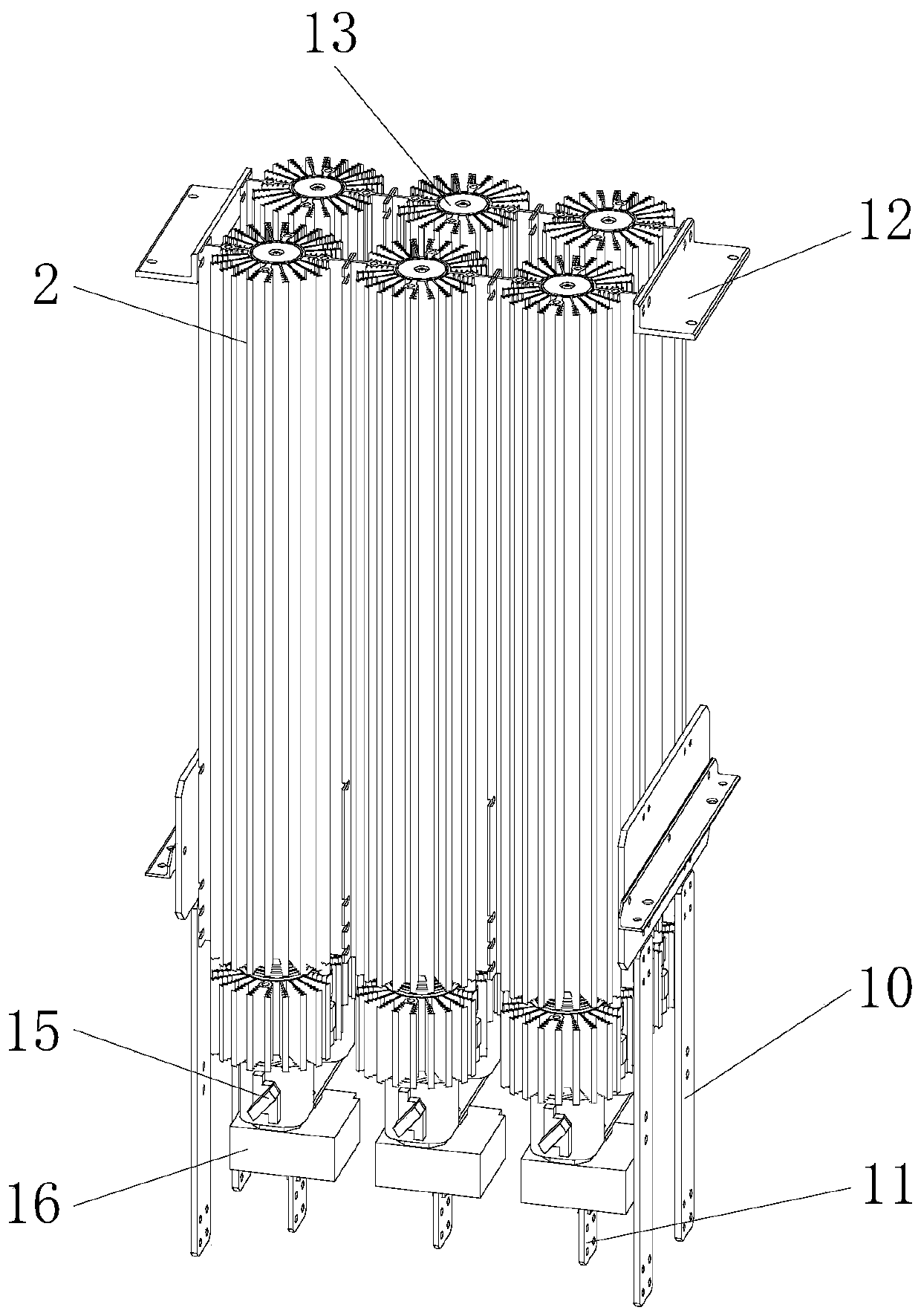
Sectional bar evaporation condenser type self-cooling rectification cabinet

A technology of evaporative condenser and rectifier cabinet, which is applied in cooling/ventilation/heating transformation, conversion of AC power input to DC power output, electrical equipment structural parts, etc. problems, to achieve the effect of increasing the heat dissipation and evaporation area, noiseless equipment operation, and uniform thermal conductivity.

Active Publication Date: 2020-07-14
郭培囵
View PDF5 Cites 0 Cited by
  • Summary
  • Abstract
  • Description
  • Claims
  • Application Information

AI Technical Summary

Problems solved by technology

[0002] At present, AC-DC rectifiers in the field of power electronics mostly adopt air-cooling and water-cooling methods. The manufacturing cost of the radiator is high, the process is complicated, and the weight is heavy. The aluminum radiator is bulky and the heat dissipation capacity is limited.
The use of water-cooling method will increase the cost and maintenance workload, and the water-cooling system occupies a large area, and the leakage of the waterway will pose a safety hazard for equipment operation. The traditional rectifier cabinet has no temperature monitoring system and cannot monitor the real-time working temperature of power electronic devices in real time. Traditional cabinets Using carbon steel and sheet metal structure, there is insufficient corrosion resistance, and the painting of the cabinet body will be polluted. The profile evaporative condenser type self-cooling rectifier cabinet is a good choice for cost performance

Method used


Image

  • Sectional bar evaporation condenser type self-cooling rectification cabinet
  • Sectional bar evaporation condenser type self-cooling rectification cabinet
  • Sectional bar evaporation condenser type self-cooling rectification cabinet

Examples


Embodiment Construction

[0024] The following will clearly and completely describe the technical solutions in the embodiments of the present invention with reference to the accompanying drawings in the embodiments of the present invention. Obviously, the described embodiments are only some, not all, embodiments of the present invention. Based on the embodiments of the present invention, all other embodiments obtained by persons of ordinary skill in the art without making creative efforts belong to the protection scope of the present invention.

[0025] In the description of the invention, it should be noted that the terms "upper", "lower", "inner", "outer", "front end", "rear end", "both ends", "one end", "another end" etc. The indicated orientation or positional relationship is based on the orientation or positional relationship shown in the drawings, and is only for the convenience of describing the present invention and simplifying the description, rather than indicating or implying that the referre...


PUM


Abstract

The invention discloses a sectional bar evaporation condenser type self-cooling rectification cabinet. The sectional bar evaporation condenser type self-cooling rectification cabinet comprises a cabinet body and a power assembly; the cabinet body comprises a frame, a door plate, an upper cover plate, a lower cover plate, vertical beams, a supporting frame and busbar fixing terminals; the power assembly is composed of a sectional bar evaporation condenser, a power electronic device, an alternating current busbar, a direct current busbar, a fast fuse, a Hall sensor and a fixed mounting frame. Aself-cooling mode is adopted for natural cooling, noise and cost are greatly reduced, energy is saved, emission is reduced, and maintenance is avoided. With the sectional bar evaporation condenser adopted, heat conduction efficiency can be effectively improved, heat resistance is reduced, processing is convenient, appearance is tidy and concise, equipment weight is reduced, and cost is reduced. The sectional bar frame structure is convenient to install and high in corrosion resistance, so that a protection level is enhanced, and standardized production is facilitated, and the problem that a traditional rectification cabinet body consumes energy, generates large noise, is poor in a heat dissipation effect, is exposed to potential safety hazards, and fails to monitor the real-time working temperature of a power electronic device in real time is solved.

Description

technical field [0001] The invention relates to the technical field of power electronics, in particular to a self-cooling rectifier cabinet with a profile evaporation condenser. Background technique [0002] At present, AC-DC rectifiers in the field of power electronics mostly adopt air-cooling and water-cooling methods. The manufacturing cost of the radiator is high, the process is complicated, and the weight is heavy. The aluminum profile radiator is bulky and the heat dissipation capacity is limited. The use of water-cooling method will increase the cost and maintenance workload, and the water-cooling system occupies a large area, and the leakage of the waterway will pose a safety hazard for equipment operation. The traditional rectifier cabinet has no temperature monitoring system and cannot monitor the real-time working temperature of power electronic devices in real time. Traditional cabinets The use of carbon steel and sheet metal structure has insufficient corrosion...

Claims


Application Information

Patent Timeline
Patent Type & Authority Applications(China)
IPC IPC(8): H02M7/00H05K7/20
CPCH02M7/003H05K7/209H05K7/20909
Inventor 郭培囵
Owner 郭培囵
Why Eureka
Try Eureka