Intelligent hydrological survey equipment

A hydrological survey and equipment technology, which is applied to underwater operation equipment, open-air water source surveys, and measurement devices, can solve problems such as inability to obtain underwater data conveniently, and achieve the effect of ensuring balance

Active Publication Date: 2020-07-17
刘红广
View PDF5 Cites 0 Cited by
  • Summary
  • Abstract
  • Description
  • Claims
  • Application Information

AI Technical Summary

Problems solved by technology

[0006] The purpose of this invention is to solve the problem that the underwater data cannot be obtained conveniently when surveying in rivers, and a kind of intelligent hydrological survey equipment is proposed

Method used


Image

  • Intelligent hydrological survey equipment
  • Intelligent hydrological survey equipment
  • Intelligent hydrological survey equipment

Examples


Embodiment 1

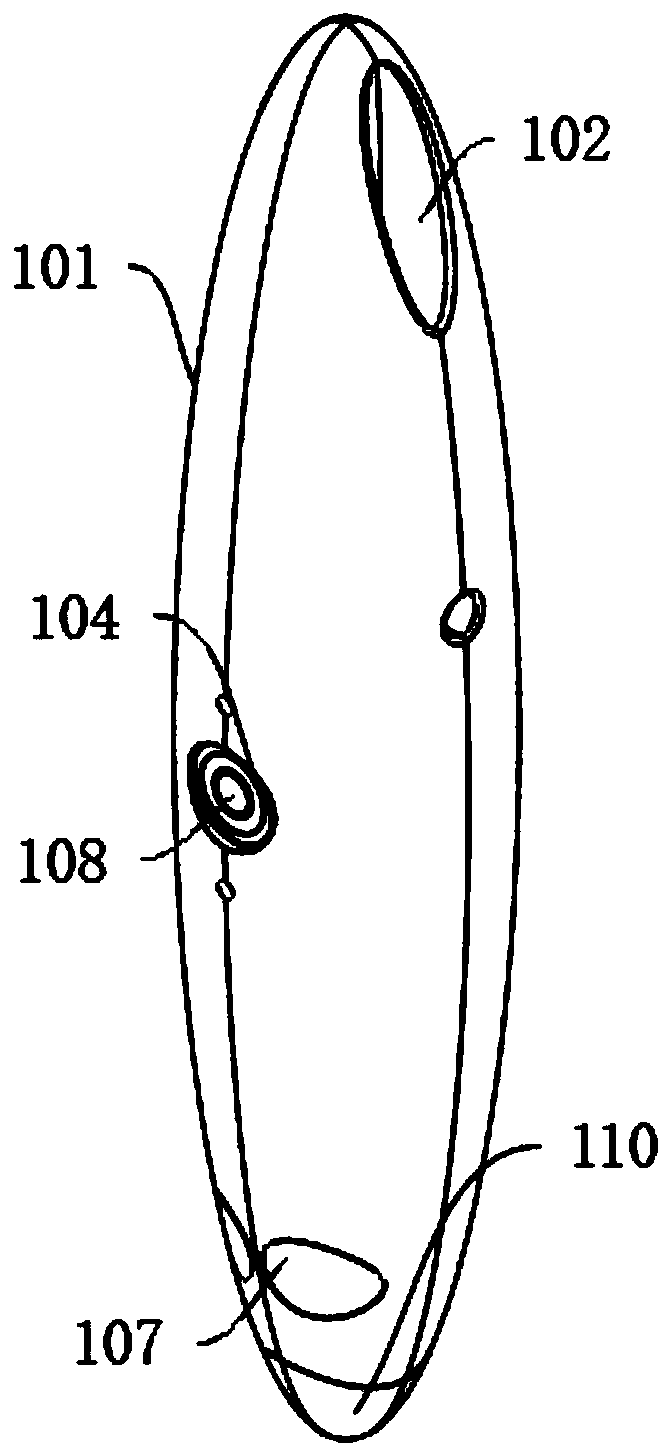
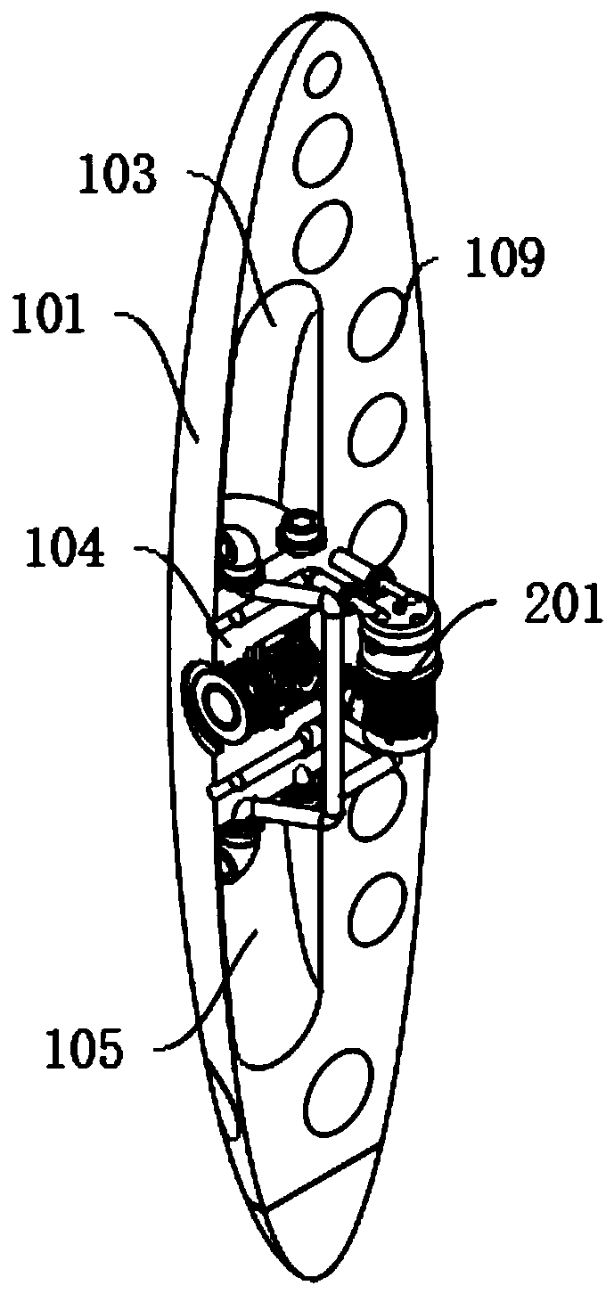
[0031] An intelligent hydrological survey equipment, including: an olive-shaped shell 101, a tail drive compartment 102, a rear counterweight compartment 103, a middle detection compartment 104, a front counterweight compartment 105, and a flexible buffer compartment 110, and the interior of the olive-shaped shell 101 is sequentially arranged from top to bottom A rear counterweight bin 103, a central detection bin 104, a front counterweight bin 105, and a flexible buffer bin 110 are provided, and the rear counterweight bin 103 is provided with a tail drive bin 102 on the left and right sides, and the tail drive bin 102 is a communication slot with openings on both sides. , the drive engine 106 is fixedly installed inside the rear drive bin 102, and the rear counterweight bin 103 and the front counterweight bin 105 are all provided with water inlets and water outlets, and the water inlets and water outlets inside the rear counterweight bin 103 and the front counterweight bin 105 ...

Embodiment 2

[0034] Embodiment 2: Based on Embodiment 1, the difference is:

[0035] The counterweight mechanism includes: a counterweight pump 201 and a three-way connection pipe 202. The left and right sides of the middle detection chamber 104 are fixedly installed with a counterweight pump 201. The water inlet and water outlet inside the front counterweight bin 105 are fixedly connected, the three-way connecting pipe 202 is located at the junction of the three-way and is provided with a solenoid valve, and the other running nozzle of the counterweight pump 201 is fixedly connected with the external environment through the pipeline, and the counterweight The connection between the other running nozzle of the pump 201 and the outside world is located at the upper and lower sides of the middle detection chamber 104 .

[0036] The present invention is provided with a counterweight mechanism, and after the counterweight pump 201 sucks water from the water inlet, it is transported to the insi...

Embodiment 3

[0037] Embodiment 3: Based on Embodiment 1 and 2, but the difference is:

[0038] The dragging mechanism includes: servo motor 301, rotating wheel 302, rotating wheel group 303, limit wheel 304, transmission shaft 305, transmission wheel 306, limit shaft 307, rotating disk 308 and rotating wire wheel 309, and the middle detection bin 104 right Servo motors 301 are fixedly installed on the upper and lower sides of the side, and the main shaft of the servo motor 301 is fixedly installed with a rotating wheel group 303, a rotating wheel 302, and a recovery fixing mechanism from right to left. The right side of the shaft 305 is fixedly connected, the middle part of the transmission shaft 305 is fixedly connected with the axis of the transmission wheel 306, the inner side of the rotating wheel 302 and the transmission wheel 306 is movably connected with the outer side of the rotating disc 308, and the upper and lower sides of the rotating disc 308 are connected with the limit The i...


PUM


Abstract

The invention discloses intelligent hydrological survey equipment, and belongs to the field of hydrological survey. According to the equipment, the whole structure is divided into a tail driving bin,a rear balance weight bin, a middle detection bin, a front balance weight bin and a flexible buffering bin, so that the balance of the whole structure is ensured; the operation posture of the equipment is monitored through a posture sensor, the rear balance weight bin and the front balance weight bin are controlled through a balance weight mechanism to maintain the overall posture of the equipment, and the whole structure of the equipment is streamline, and therefore, the phenomenon that the equipment is wound and trapped by substances such as aquatic plants during running in rivers can be well avoided, and the equipment monitors the landform of the bottoms of the rivers and the flow of water bodies by adopting a dragging sonar, so that the problem that the equipment cannot enter deep water bodies is avoided.

Description

technical field [0001] The invention relates to the field of hydrological survey, in particular to an intelligent hydrological survey device. Background technique [0002] In the early 1980s, the traditional hydrological station test mode could no longer meet the development of hydrological survey station business. On the basis of the original station station mode, the hydrological industry tried out the test method of station team combination. In 1986, the former Ministry of Water and Electricity promulgated the "Hydrological "Trial Measures for the Joint Survey of Stations and Teams" to standardize the test method. In the 1990s, in order to adapt to the changes in the hydrological system, further promote the combination of hydrological survey station and team test methods, standardize survey technology, and ensure the quality of survey results, the Department of Hydrology of the Ministry of Water Resources presided over the compilation of SL195-97 "Specifications for Hydro...

Claims


Application Information

Patent Timeline
Patent Type & Authority Applications(China)
IPC IPC(8): B63C11/52B63G8/00B63G8/26B63G8/39G01C13/00
CPCB63C11/52B63G8/001B63G8/26B63G8/39G01C13/002
Inventor 邹可可周军亭郭广涛史靖雯杨力左惠玲郭艳艳郭晓潇刘帅华刘红广
Owner 刘红广
Why Eureka
Try Eureka