
Integrated treatment device for high-concentration sewage

A sewage treatment device and technology for sewage treatment, applied in water/sewage treatment, water/sewage multi-stage treatment, water/sludge/sewage treatment, etc. and other problems, to achieve the effect of small footprint, convenient management, simple and compact structure

Inactive Publication Date: 2020-07-17
广州森洋环保设备有限公司
View PDF4 Cites 0 Cited by
  • Summary
  • Abstract
  • Description
  • Claims
  • Application Information

AI Technical Summary

Problems solved by technology

[0003] As the centralized sewage treatment method solves the water pollution problem that people are concerned about, centralized sewage treatment has become the main way of urban sewage treatment, and because the traditional sewage treatment process is relatively cumbersome, it leads to a large area and inconvenient management. , so there is room for improvement

Method used


Image

  • Integrated treatment device for high-concentration sewage
  • Integrated treatment device for high-concentration sewage
  • Integrated treatment device for high-concentration sewage

Examples


Embodiment 1

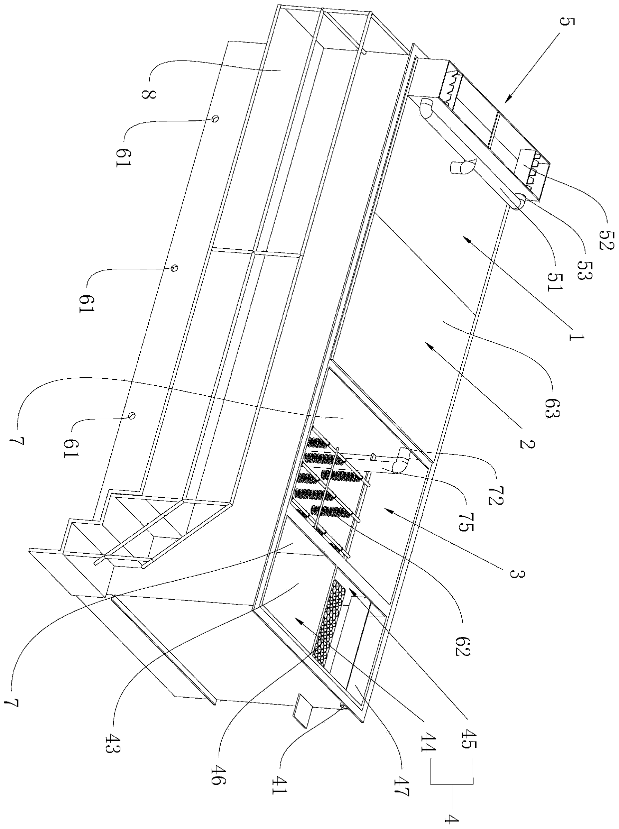
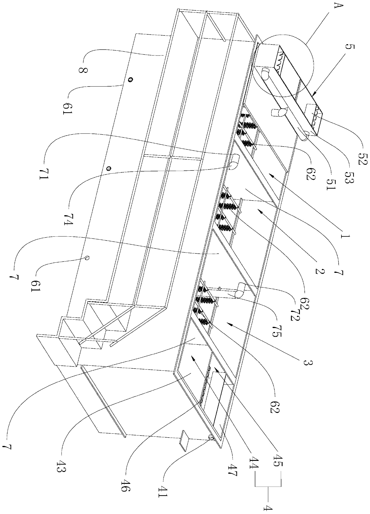
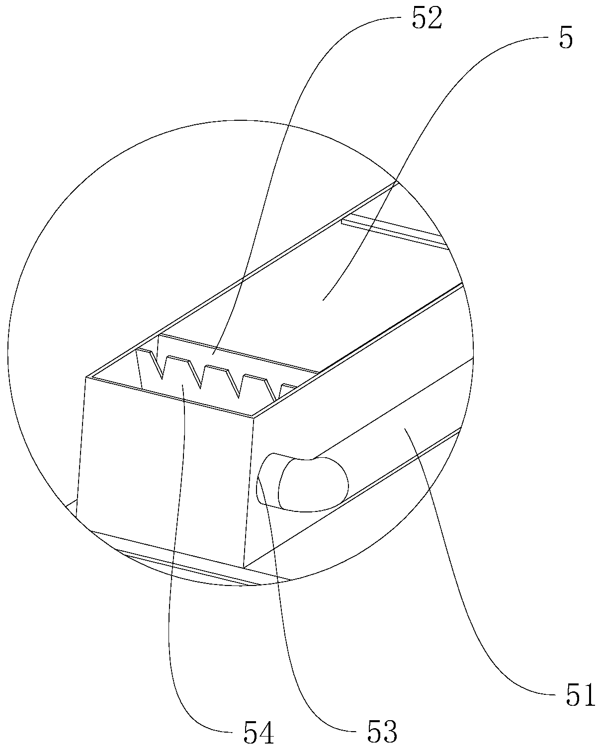
[0039] refer to figure 1 , is a high-concentration integrated sewage treatment device disclosed by the present invention, comprising a sewage treatment tank with an opening and a walking platform 8 located on the side wall of the sewage treatment tank. The welded barrier plate 7, the sewage treatment tank is divided into the separation tank 1, the anaerobic tank 2, the oxidation tank 3 and the filter tank 4 connected in sequence through the barrier plate 7; the barrier plate 7 in the separation tank 1 and the anaerobic tank 2 is shown in the figure Not shown; the bottom of the sewage treatment tank is provided with four sludge discharge outlets 61 respectively connected to the separation tank 1, anaerobic tank 2, oxidation tank 3 and filter tank 4, and the sludge discharge outlet 61 at the bottom of the filter tank 4 is not shown, A sludge pump for controlling its extraction is provided at the sludge outlet 61, which is not shown in the figure; an outlet pipe 41 is connected t...

Embodiment 2

[0052] Such as Figure 5 As shown, the difference between Embodiment 2 and Embodiment 1 is that in Embodiment 2, a horizontal support plate 11 protrudes from the end of the separation tank 1 facing away from the anaerobic tank 2, and the water inlet tank 5 is placed on the support plate 11. , the support plate 11 below is placed with some control boxes 12 for controlling the work of different sewage pumps in the sewage treatment tank, which is convenient for the staff to place the control boxes 12, and the later maintenance and operation are more convenient.

Embodiment 3

[0054] combine figure 2 and Figure 6 It can be seen that the difference between the third embodiment and the first embodiment is that a low-pressure connecting pipe 31 is provided at the oxidation water conduit 75 and the second through hole 72, and the diameter of the low-pressure connecting pipe 31 gradually increases from the center to both ends. A one-way valve 311 is installed at the smallest diameter of 31; when the sewage in the anaerobic tank 2 passes through the low-pressure connecting pipe 31, a low-pressure area is generated in the low-pressure connecting pipe 31 due to the reduction of the diameter of the low-pressure connecting pipe 31, so that the one-way The outside air at the valve 311 is sucked into the low-pressure connecting pipe 31, and when the sewage passes through a section where the diameter of the low-pressure connecting pipe 31 gradually increases, the air pressure at this place gradually increases, and the air entering the one-way valve 311 is unde...


PUM


Abstract

The invention relates to an integrated treatment device for high-concentration sewage. The integrated treatment device comprises a sewage treatment tank, wherein a separation tank, an anaerobic tank,an oxidation tank and a filter tank which sequentially communicate with each other are arranged in the sewage treatment tank; a water inlet tank is connected to one end, back to the anaerobic tank, ofthe separation tank; the filter tank communicates with a water outlet pipe; sludge outlets are formed in the bottoms of the separation tank, the anaerobic tank, the oxidation tank and the filter tank; and dominant microbial fillers are placed in the separation tank, the anaerobic tank and the oxidation tank. According to the invention, sewage is separated from deposited sludge through the separation tank; anaerobic bacteria are added into the anaerobic tank to hydrolyze and acidify organic matters in the sewage, so the content of the organic matters in the sewage is reduced, and anaerobic degradation products provide rich carbon sources for denitrification nitrogen removal; and the separation tank, the anaerobic tank, the oxidation tank and the filter tank are simple and compact in structure, small in occupied area and convenient to manage.

Description

technical field [0001] The invention relates to the technical field of environmental protection water treatment, in particular to a high-concentration integrated sewage treatment device. Background technique [0002] At present, with the rapid development of social economy, people's demand and consumption of water resources are also increasing, the amount of sewage discharge is increasing, the types and concentrations of pollutants are increasing, water pollution is becoming more and more serious, and eutrophic water bodies are increasing. [0003] As the centralized sewage treatment method solves the water pollution problem that people are concerned about, centralized sewage treatment has become the main way of urban sewage treatment, and because the traditional sewage treatment process is relatively cumbersome, it leads to a large area and inconvenient management. , so there is room for improvement. Contents of the invention [0004] In view of the deficiencies in the p...

Claims


Application Information

Patent Timeline
Patent Type & Authority Applications(China)
IPC IPC(8): C02F9/14C02F101/30C02F101/16
CPCC02F1/001C02F1/5281C02F3/30C02F7/00C02F9/00C02F2001/007C02F2101/16C02F2101/30
Inventor 钟友方
Owner 广州森洋环保设备有限公司
Learn More