
Toxic flammable gas processing and reusing method for liquid produced from oil well and special device

A technology of flammable gas and special devices, which is applied in the field of toxic and flammable gas treatment and reuse methods and special devices for oil well production fluids, and in the field of toxic and flammable gas treatment and reuse methods and special devices for heavy oil well production fluids. Solve the problems of high labor cost and waste of heat energy, etc., and achieve the effect of preventing environmental pollution, saving energy waste, and huge investment

Active Publication Date: 2020-07-17
XINJIANG HUALONG OILFIELD TECHNOLOGICAL LIABILITY +1
View PDF20 Cites 1 Cited by
  • Summary
  • Abstract
  • Description
  • Claims
  • Application Information

AI Technical Summary

Problems solved by technology

[0004] The invention provides a method and special device for treating and reusing toxic and flammable gases in oil well production fluid, which overcomes the above-mentioned deficiencies in the prior art, and can effectively solve the problem of removing toxic and flammable gases in the existing heavy oil thermal production fluid The method wastes heat energy and high labor costs

Method used


Image

  • Toxic flammable gas processing and reusing method for liquid produced from oil well and special device

Examples


Embodiment 1

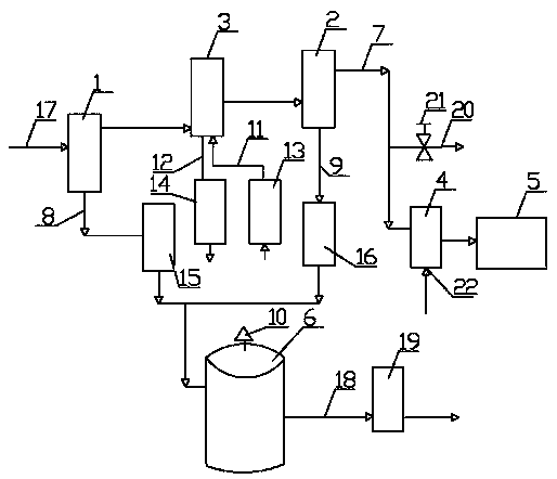
[0018] Example 1: Toxic and flammable gas treatment and reuse method of oil well production fluid, single well fluid (heavy oil thermal production fluid) undergoes the first gas-liquid separation to obtain the first separated gas phase and the first separated liquid phase The gas-liquid mixture is obtained by the first separation of the gas phase through water-cooling heat exchange, the gas-liquid mixture is separated by the second gas-liquid separation to obtain the toxic and flammable gas and the second separation of the liquid phase, and the toxic and flammable gas is sent through the ejector 4 The combustion chamber of the gas-fired boiler 5 burns; the first separation of gas-phase water-cooled heat exchange and cooling water comes from the water of the gas-fired boiler 5, and the return water after the first separation of gas-phase water-cooled heat exchange and cooling returns to the gas-fired boiler 5.

[0019] This method adopts the water-cooling method instead of the e...

Embodiment 2

[0020] Embodiment 2: as attached figure 1 As shown, the special device includes a first gas-liquid separator 1, a second gas-liquid separator 2, a water-cooled heat exchanger 3, an ejector 4, a gas boiler 5 and an oil storage tank 6, and the first gas-liquid separator 1 The gas outlet is connected to the inlet of the hot fluid passage of the water-cooled heat exchanger 3, the outlet of the hot fluid passage of the water-cooled heat exchanger 3 is connected to the inlet of the second gas-liquid separator 2, and the gas outlet of the second gas-liquid separator 2 is connected to the ejector The hydrogen sulfide gas pipeline 7 is connected between the left ports of 4, the gas outlet end of the ejector 4 is connected with the gas inlet end of the gas boiler 5, the liquid outlet end of the first gas-liquid separator 1 is connected with the liquid inlet end of the oil storage tank 6 It is communicated through the first liquid inlet line 8, the liquid outlet end of the second gas-liq...


PUM


Abstract

The invention relates to the field of desulphuration technologies for hot liquid produced from thickened oil, in particular to a toxic flammable gas processing and reusing method for liquid produced from an oil well and a special device. Twice gas-liquid separation is performed on liquid from a single well, and toxic flammable gases including hydrogen sulfide, obtained by separation, enter a gas-fired boiler via a jet device to be burnt. A water-cooling method replaces the conventional air-cooling method, and the toxic gases including hydrogen sulfide, obtained after cooling, are gathered in the gas-fired boiler by the jet device to participate in combustion, such that energy waste is reduced and environmental pollution is prevented. In addition, hydrogen sulfide gas is gathered in gas ofthe gas-fired boiler by the jet device, and no hydrogen sulfide gas and alkaline liquor neutralization device needs to be added. Since less toxic flammable gas is produced after heat exchange, coolingand liquidation, building a special gas collection device is huge in investment but produces very little effect. By use of the special device, building a gas collection device is not required, desulphuration is achieved, and heat energy can be reused.

Description

technical field [0001] The invention relates to the technical field of gas treatment of oilfield produced fluid, and is a method and special device for treating and reusing toxic and flammable gas in oil well produced fluid, especially a method for treating and reusing toxic and flammable gas in heavy oil well produced fluid and special devices. Background technique [0002] In the exploitation of heavy crude oil in oilfields, the thermal recovery method of injecting high-temperature and high-pressure steam into the oil layer is often used to reduce the viscosity of crude oil. The oil well production fluid contains a large amount of combustible gas, hydrogen sulfide, and high-temperature water vapor. These production fluids are collected into the oil storage tank, and the gas flows from The roof of the oil storage tank escapes, and the escaping combustible gas and hydrogen sulfide will pose a great threat to the environment and personnel safety, and the escaping high-tempera...

Claims


Application Information

Patent Timeline
Patent Type & Authority Applications(China)
IPC IPC(8): E21B43/34E21B41/00F25D1/02F23G7/06G05D27/02
CPCE21B43/34E21B41/0071F25D1/02F23G7/06G05D27/02
Inventor 王方白刚党延辉赵志华马晓军哈德力·哈布都斯张宏伟张少阳
Owner XINJIANG HUALONG OILFIELD TECHNOLOGICAL LIABILITY
Learn More