
Negative obstacle detection method and device, terminal equipment and storage medium

An obstacle detection and obstacle technology, applied in the field of robotics, can solve problems such as waste of resources, achieve the effect of reducing processing capacity and saving computing resources

Pending Publication Date: 2020-07-17
GUANGZHOU SHIYUAN ELECTRONICS CO LTD
View PDF3 Cites 8 Cited by
  • Summary
  • Abstract
  • Description
  • Claims
  • Application Information

AI Technical Summary

Problems solved by technology

[0006] The present invention provides a negative obstacle detection method, device, terminal equipment and storage medium to solve the technical problem of waste of resources caused by a large amount of invalid data management by the server and the client when multi-party remote voice interaction is performed for audio transmission in the prior art

Method used


Image

  • Negative obstacle detection method and device, terminal equipment and storage medium
  • Negative obstacle detection method and device, terminal equipment and storage medium
  • Negative obstacle detection method and device, terminal equipment and storage medium

Examples


Embodiment 1

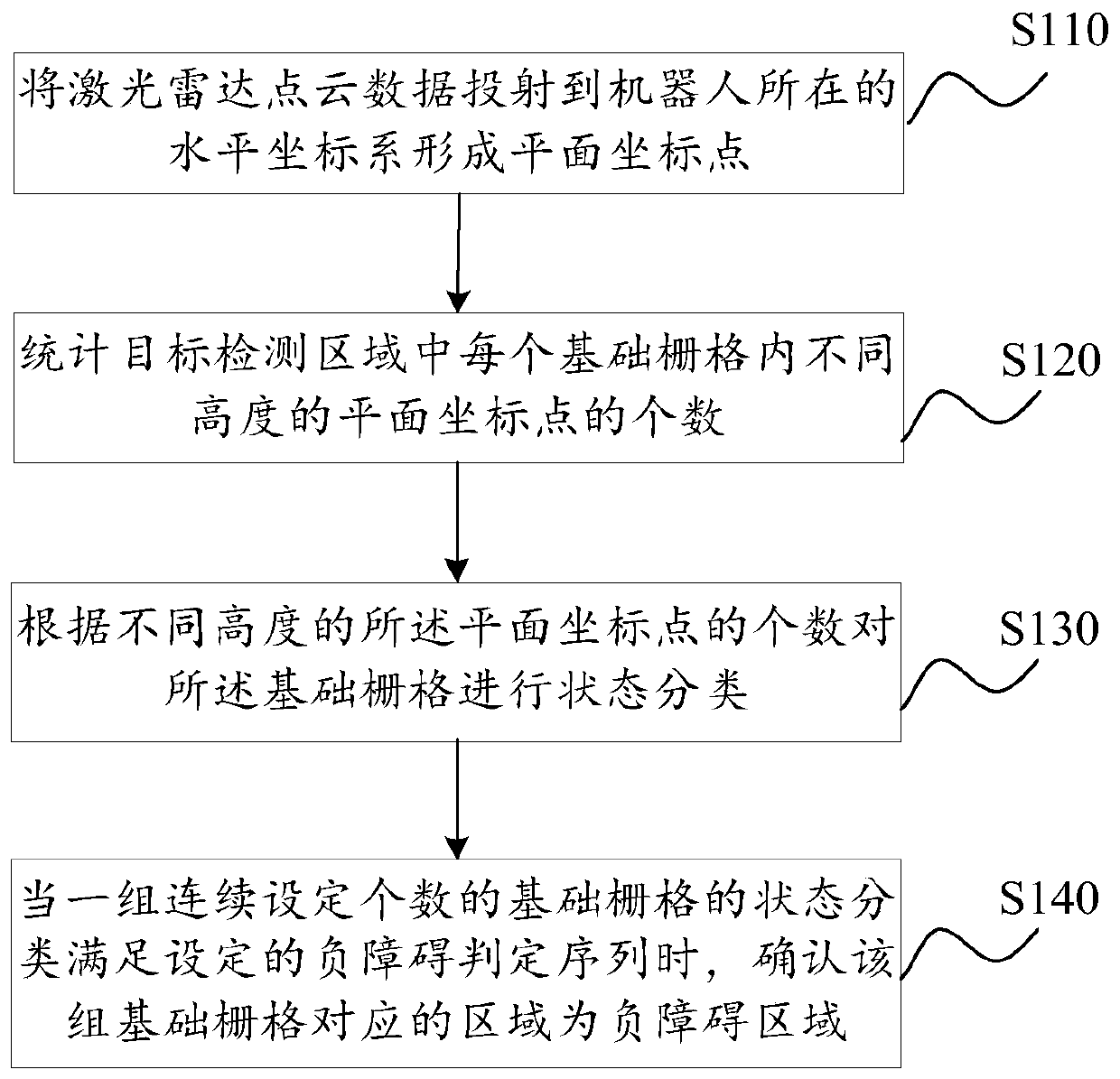
[0056] figure 2 It is a flowchart of a negative obstacle detection method provided by Embodiment 1 of the present invention. The negative obstacle detection method provided in the embodiment can be performed by an audio transmission device, which can be realized by software and / or hardware. The audio transmission device can be composed of two or more physical entities, or can be A physical entity constitutes. For example, an audio transmission device can be a mobile phone, an industrial control computer, etc.

[0057] Step S110: Project the lidar point cloud data to the horizontal coordinate system where the robot is located to form plane coordinate points.

[0058] The point cloud data detected by the lidar is three-dimensional coordinate data, and each point cloud data passes the distance from the origin in three two-by-two perpendicular dimensions (such as the forward direction, the lateral and vertical directions perpendicular to the forward direction), Characterizes t...

Embodiment 2

[0069] Figure 4 It is a flow chart of a negative obstacle detection method provided by Embodiment 2 of the present invention. This embodiment is embodied on the basis of the above-mentioned embodiments.

[0070] Specifically, refer to Figure 4 , the negative obstacle detection method provided in this embodiment specifically includes:

[0071] Step S201: Map the lidar point cloud data to the robot coordinate system to obtain environment point cloud data.

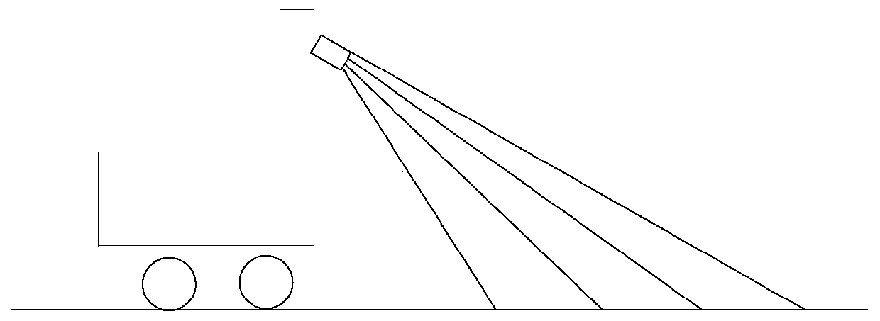
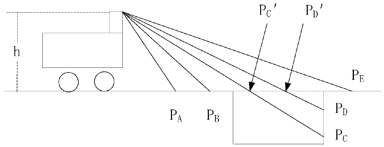
[0072] The laser radar coordinate system is established with the laser radar as the coordinate origin. The laser radar output is generally point cloud data in the laser radar coordinate system. Knowing the installation position of the laser radar on the robot, the environment based on the robot coordinate system can be calculated. point cloud data. Generally speaking, the direction of the lidar is at a certain angle with the horizontal direction. The design of the angle enables the robot to identify obstacles below its ...

Embodiment 3

[0086] Figure 6 It is a schematic structural diagram of a negative obstacle detection device provided in Embodiment 3 of the present invention. refer to Figure 6 , the negative obstacle detection device includes: a coordinate projection unit 310, a quantity statistics unit 320, a grid classification unit 330 and a sequence judgment unit 340.

[0087] The coordinate projection unit 310 is used to project the lidar point cloud data to the horizontal coordinate system where the robot is located to form plane coordinate points; the quantity statistics unit 320 is used to count the plane coordinate points of different heights in each basic grid in the target detection area The target detection area is located in the horizontal coordinate system, and the grid composed of the basic grid covers the target detection area; the grid classification unit 330 is used for The number classifies the state of the basic grids; the sequence judging unit 340 is used to confirm the group of ba...


PUM


Abstract

The embodiment of the invention discloses a negative obstacle detection method and device, terminal equipment and a storage medium. The method comprises the steps of projecting laser radar point clouddata to a horizontal coordinate system where a robot is located to form plane coordinate points; counting the number of plane coordinate points with different heights in each basic grid in a target detection area, the target detection area being located in the horizontal coordinate system, and a grid formed by the basic grids covering the target detection area; performing state classification onthe basic grids according to the number of the plane coordinate points with different heights; and when the state classification of a group of continuously set number of basic grids meets a set negative obstacle judgment sequence, determining that an area corresponding to the group of basic grids is a negative obstacle area. According to the method for segmenting the negative obstacle from the original point cloud by fusing multiple frames of data, the problem of low processing precision of single-frame data can be avoided, the negative obstacle is detected through arrangement characteristics,and computing resources can be effectively saved.

Description

technical field [0001] The embodiments of the present invention relate to the field of robot technology, and in particular, to a negative obstacle detection method, device, terminal equipment, and storage medium. Background technique [0002] With the continuous development of electronic technology, robot technology has begun to be applied to all aspects of social production and life. Simultaneously with the expansion of the scope of use of robots is the rapid development of external obstacle detection technology. To meet the needs of various external obstacle detection, technologies such as infrared image acquisition and detection, optical image acquisition and detection, and laser radar detection are continuously integrated, developed and applied in the field of robots. Obtain fast and accurate obstacle detection results. [0003] A method of using laser to detect negative obstacles (generally impassable obstacles lower than the ground level, such as pits, ravines, cliffs...

Claims


Application Information

Patent Timeline
IPC IPC(8): G06T7/77G06T7/11G06T5/50G06T3/00G06K9/62
CPCG06T7/77G06T7/11G06T5/50G06T2207/10028G06F18/24G06T3/06
Inventor 吴华勃
Owner GUANGZHOU SHIYUAN ELECTRONICS CO LTD
Learn More