Wood smashing device for building construction

A technology for building construction and crushing device, which is applied to wood processing appliances, cleaning methods using liquids, manufacturing tools, etc., can solve problems such as influence, poor treatment methods, waste of resources and environment, etc., and achieves wide cleaning area and resource utilization efficiency. high cleaning efficiency

Inactive Publication Date: 2020-07-24
陈元定
View PDF0 Cites 0 Cited by
  • Summary
  • Abstract
  • Description
  • Claims
  • Application Information

AI Technical Summary

Problems solved by technology

[0004] The main purpose of the present invention is to provide a wood crushing device for building construction to solve the problems of poor post-use treatment of existing building wood, resulting in waste of resources and environmental impact.

Method used


Image

  • Wood smashing device for building construction
  • Wood smashing device for building construction
  • Wood smashing device for building construction

Examples


Embodiment 1

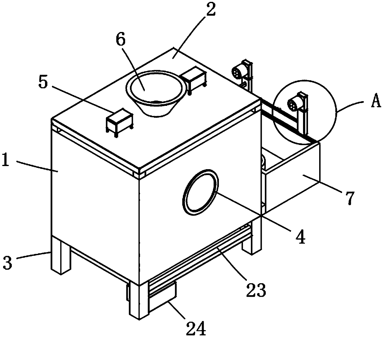
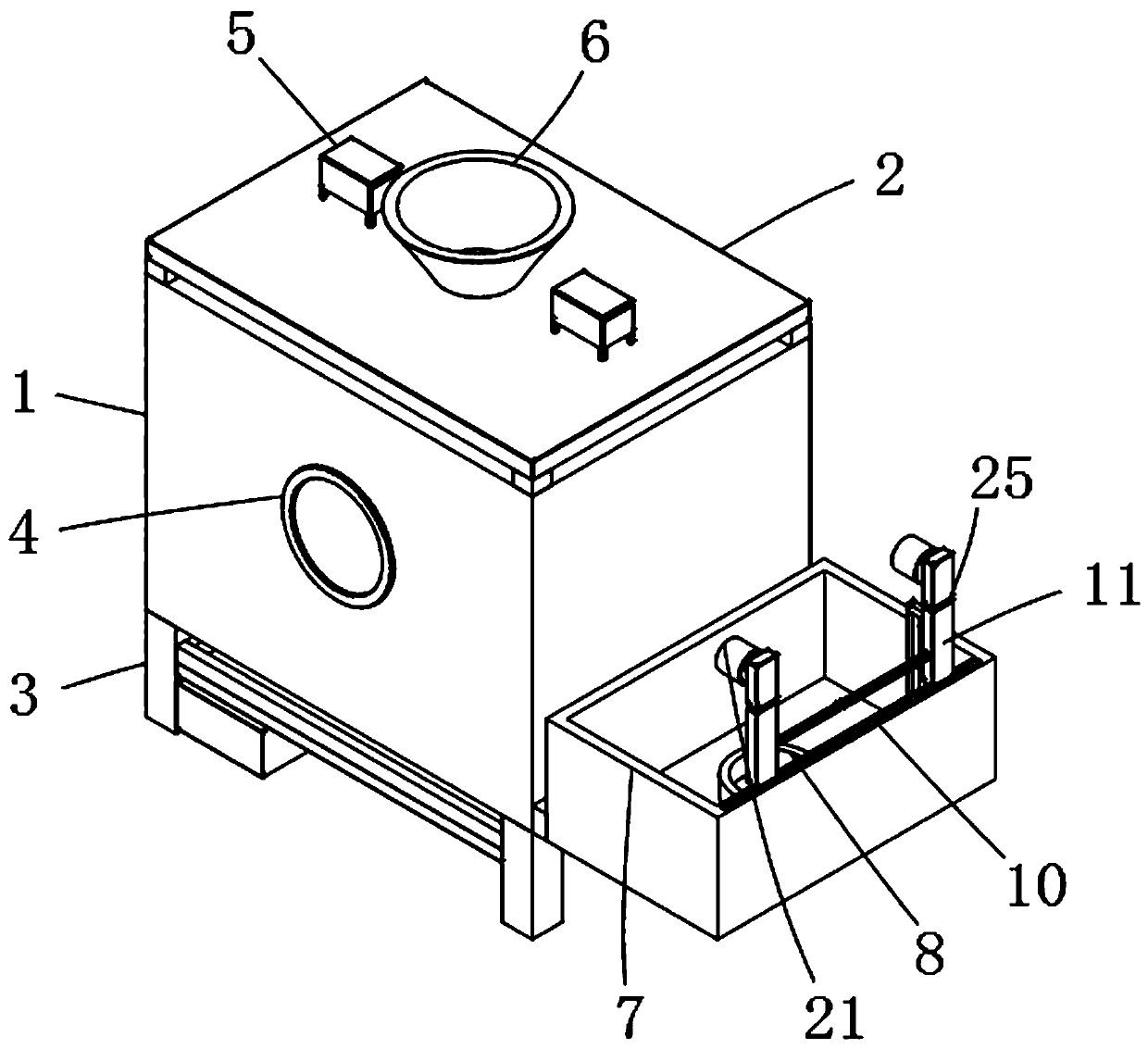
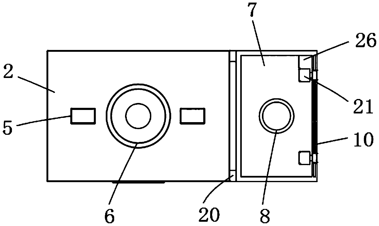
[0029] Please refer to Figure 1-8 Shown: a wood crushing device for building construction, including a box body 1, a cover plate 2 and support legs 3, the cover plate 2 is snap-connected to the upper end of the box body 1, and several support legs are fixedly connected to the bottom end of the box body 1 3. The surface of the box body 1 is provided with a feed port 6, the upper surface of the cover plate 2 is installed with an electric push rod 5, and the inside of the box body 1 is provided with a push plate 9, and the output end of the electric push rod 5 penetrates the cover plate 2 and extends into the box body 1 is connected with the push plate 9 inside, a drive motor 16 is installed at the bottom end of the box body 1, a drive shaft 17 is connected to the output end of the drive motor 16, a crushing rod 19 is arranged at the bottom end inside the box body 1, and a first A telescopic shaft 18, the crushing rod 19 is connected with the first telescopic shaft 18, the drivi...

Embodiment 2

[0031] Please refer to Figure 1-8Shown: cleaning tank 7 interior is provided with water pump 26, and the output end of water pump 26 is connected with guide tube 13, and guide rod 11 is connected with guide tube 13, utilizes water pump 26 to guide the cleaning water source of timber through guide tube 13 to The guide rod 11 is guided by the guide rod 11 to the spray nozzle 21 for spraying. The guide rod 11 is provided with two groups, and a shunt pipe 14 is connected between the two groups of guide rods 11. Spray cleaning efficiency, the observation port 4 is provided on one side of the box body 1, which is convenient for instant observation of the processing state of the wood, and the use of the lifting device is controllable. A fixed block 20 is connected between the box body 1 and the cleaning tank 7. The block 20 is connected and fixed, and the use stability is stronger. One end of the guide rod 11 is connected with a second telescopic shaft 25, which is convenient for ad...


PUM


Abstract

The invention discloses a wood smashing device for building construction, and relates to the technical field of building machinery. The wood smashing device comprises a box, a cover plate and supporting legs, the cover plate is connected to the upper end of the box in a buckling mode, the multiple supporting legs are fixedly connected to the bottom end of the box, a feeding opening is formed in the surface of the box, an electric push rod is installed on the upper surface of the cover plate, and a push plate is arranged in the box. The output end of the electric push rod penetrates through thecover plate to stretch into the box to be connected with the push plate, a drive motor is installed at the bottom end of the box, a drive shaft is connected to the output end of the drive motor, anda smashing rod is arranged at the bottom end of the interior of the box. A first telescopic shaft is connected to one end of the drive shaft, the smashing rod is connected with the first telescopic shaft, an undertake slot is formed in the lower part of the box, a filter screen is arranged on the inner surface of the bottom end of the box, and the filter screen is located below the smashing rod. According to the wood smashing device for the building construction, the smashing rod is used for transversely cutting and smashing woods, the push plate in the box is used for longitudinal extrusion,so that the woods are more concentrated, the fineness is high during smashing, and later further processing is facilitated.

Description

technical field [0001] The invention relates to the technical field of construction machinery, in particular to a wood crushing device used in construction. Background technique [0002] Construction engineering refers to engineering entities formed through the construction of various housing buildings and their ancillary facilities and the installation of supporting lines, pipelines, and equipment. It is a project that forms an internal space to meet the needs of people's production, living, learning, and public activities. As the competition in the construction engineering industry continues to intensify, mergers and acquisitions among large-scale construction engineering companies and capital operations are becoming more frequent, and domestic excellent construction engineering production enterprises are becoming more and more The more attention is paid to the research on the industry market, especially the in-depth research on the industrial development environment and p...

Claims


Application Information

Patent Timeline
Patent Type & Authority Applications(China)
IPC IPC(8): B02C18/12B02C18/16B08B3/02B27L11/00
CPCB02C18/0084B02C18/12B02C18/16B02C2201/06B08B3/024B27L11/00B27L11/005
Inventor 陈元定
Owner 陈元定
Why Eureka
Try Eureka