Precision injection molding part producing and machining technology

A processing technology and technology of injection molded parts, which is applied in the direction of metal processing equipment, manufacturing tools, grinding workpiece supports, etc., can solve the problems of uneven polishing effect, easy deviation, and long working hours, so as to improve the scope of application and improve the The overall stability and the effect of improving the utilization rate

Active Publication Date: 2020-07-24
永清县亿晟金塑有限公司
View PDF6 Cites 2 Cited by
  • Summary
  • Abstract
  • Description
  • Claims
  • Application Information

AI Technical Summary

Problems solved by technology

[0003] 1. When polishing multiple surfaces of injection molded parts, the manual or mechanical one-sided polishing method takes a long time and cumbersome working steps, and the polishing effect of each surface is easily caused by human factors during the conversion and polishing process of each surface At the same time, during the polishing process, the stability of the injection molded part itself is low and it is prone to deflection, so that the polishing effect is reduced;
[0004] 2. The polishing of common injection molded parts is usually carried out when the surface of the injection molded part is in a dry state. In this state, the friction between the surface of the injection molded part and the polishing tool is relatively large, which may easily cause unnecessary wear on the surface of the injection molded part, and the polishing process The debris generated in the process is also easy to re-adhere to the surface of the injection molded part. At the same time, after the polishing tool is used for a long time, the debris layer deposited on the surface will reduce the polishing effect

Method used


Image

  • Precision injection molding part producing and machining technology
  • Precision injection molding part producing and machining technology
  • Precision injection molding part producing and machining technology

Examples


Embodiment Construction

[0044] The embodiments of the present invention will be described in detail below with reference to the accompanying drawings, but the present invention can be implemented in many different ways as defined and covered by the claims.

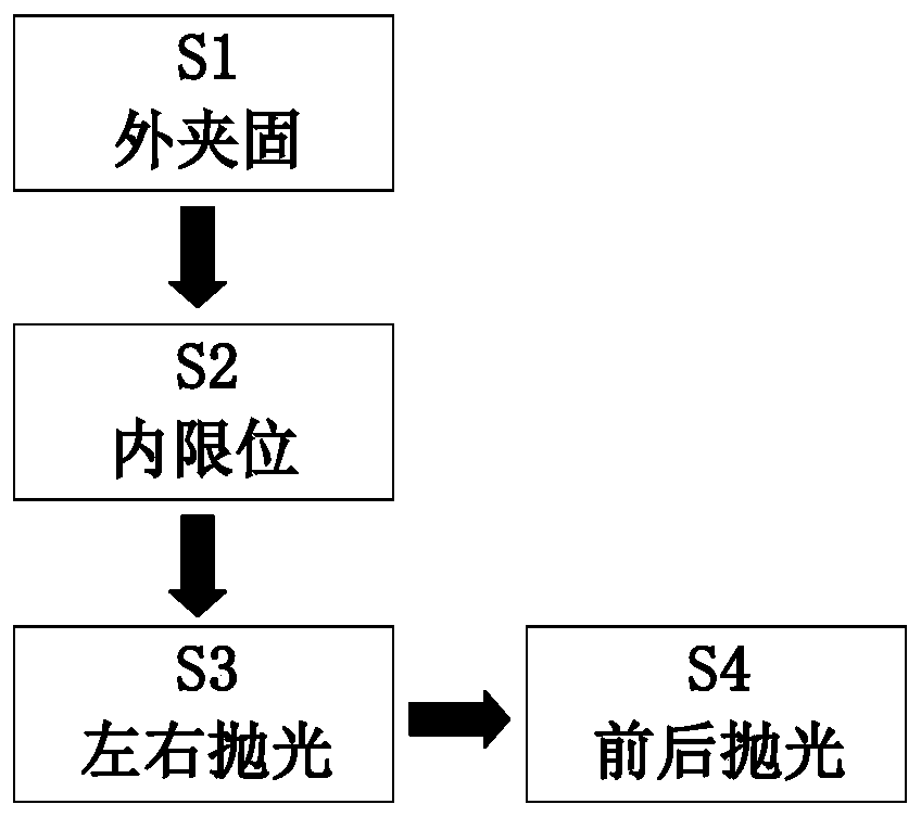
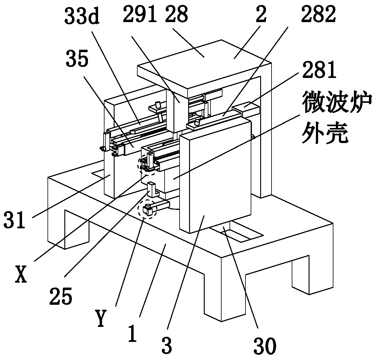
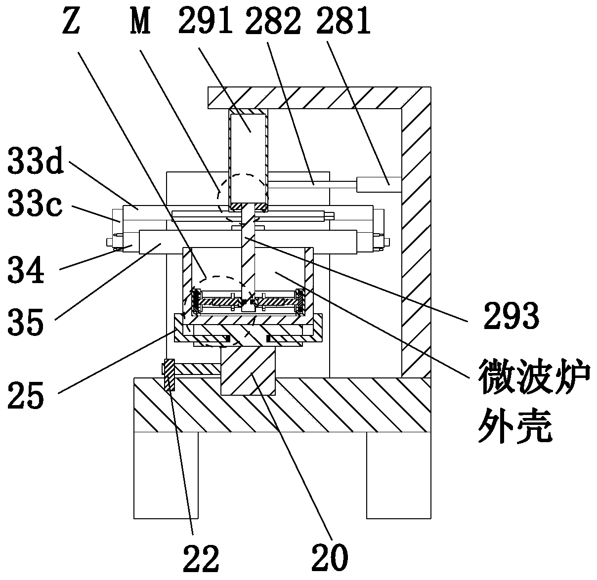
[0045] Such as Figure 1 to Figure 13 As shown, a production and processing process of precision injection molded parts uses a precision injection molded parts production and processing device. The precision injection molded parts production and processing device includes a workbench 1, a clamping mechanism 2 and a polishing mechanism 3. The specific processing technology of the production and processing device for the production and processing of precision injection molded parts is as follows:

[0046] S1. External clamping: Place the microwave oven shell on the bottom support block 23 manually, drive the No. 1 L-shaped splint 25 through the No. 1 electric slider 24, and drive the No. 2 L-shaped splint 27 to the The inner movement clamps the mi...


PUM


Abstract

The invention relates to a precision injection molding part producing and machining technology. A precision injection molding part producing and machining device is used in the precision injection molding part producing and machining technology. The precision injection molding part producing and machining device comprises a workbench, a clamping and fixing mechanism and polishing mechanisms. The clamping and fixing mechanism is mounted at the upper end of the workbench in a sliding fit manner; the polishing mechanisms are symmetrically arranged on the left side and the right side of the clamping and fixing mechanism; and the lower end of each polishing mechanism is in sliding fit with the upper end of the workbench. A design concept of a multi-direction controllable conversion structure isadopted for producing and machining a precision injection molding part; through the arrangement of a structure with a controllable clamping and fixing range, the adaption range of clamping and fixingmicrowave oven shells of different sizes and types is widened, the device can also be suitable for polishing treatment of products similar to the microwave oven shells in shape, and then the overallutilization rate of the device is greatly increased.

Description

technical field [0001] The invention relates to the technical field of injection molded parts processing, in particular to a production and processing technology of precision injection molded parts. Background technique [0002] Injection molding is a method of producing shapes for industrial products. Products usually use rubber injection molding and plastic injection molding. Injection molding can also be divided into injection molding molding method and die-casting method. Injection molding machine (referred to as injection machine or injection molding machine) is the main molding equipment for making thermoplastic or thermosetting materials into various shapes of plastic products using plastic molding molds. Injection molding is It is realized through injection molding machines and molds. Injection molded parts refer to various injection molded products produced by injection molding machines, collectively referred to as injection molded parts, including various packagin...

Claims


Application Information

Patent Timeline
Patent Type & Authority Applications(China)
IPC IPC(8): B24B29/02B24B41/02B24B41/06B24B55/06B24B27/02B24B47/04B24B45/00F26B5/16B08B3/02
CPCB08B3/02B24B27/02B24B29/02B24B41/02B24B41/06B24B45/003B24B47/04B24B55/06F26B5/16
Inventor 付子豪邵可心
Owner 永清县亿晟金塑有限公司
Why Eureka
Try Eureka