Polishing system and polishing method

A support table and operating table technology, applied in the field of polishing, can solve the problems of low polishing efficiency, high scrap rate, and high product scrap rate, and achieve the effects of improving polishing efficiency, reducing idle rate, and reducing scrap rate

Active Publication Date: 2020-07-24
NICROTEK +1
View PDF8 Cites 0 Cited by
  • Summary
  • Abstract
  • Description
  • Claims
  • Application Information

AI Technical Summary

Problems solved by technology

[0003] The traditional polishing technology is to directly stack the base materials of the light guide plate to be polished, and fix them with a baffle for processing. Because the base material of the light guide plate is provided with a boss with a height of about 1 mm, such as image 3 As shown, the base material of the stacked light guide plate is easy to tilt, so that only a small amount of

Method used


Image

  • Polishing system and polishing method
  • Polishing system and polishing method
  • Polishing system and polishing method

Examples


Embodiment Construction

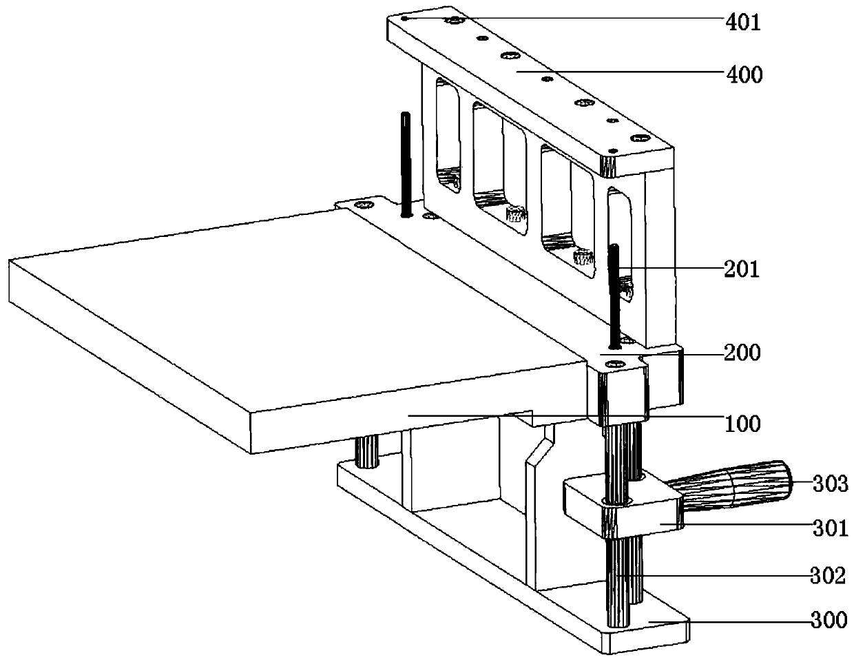
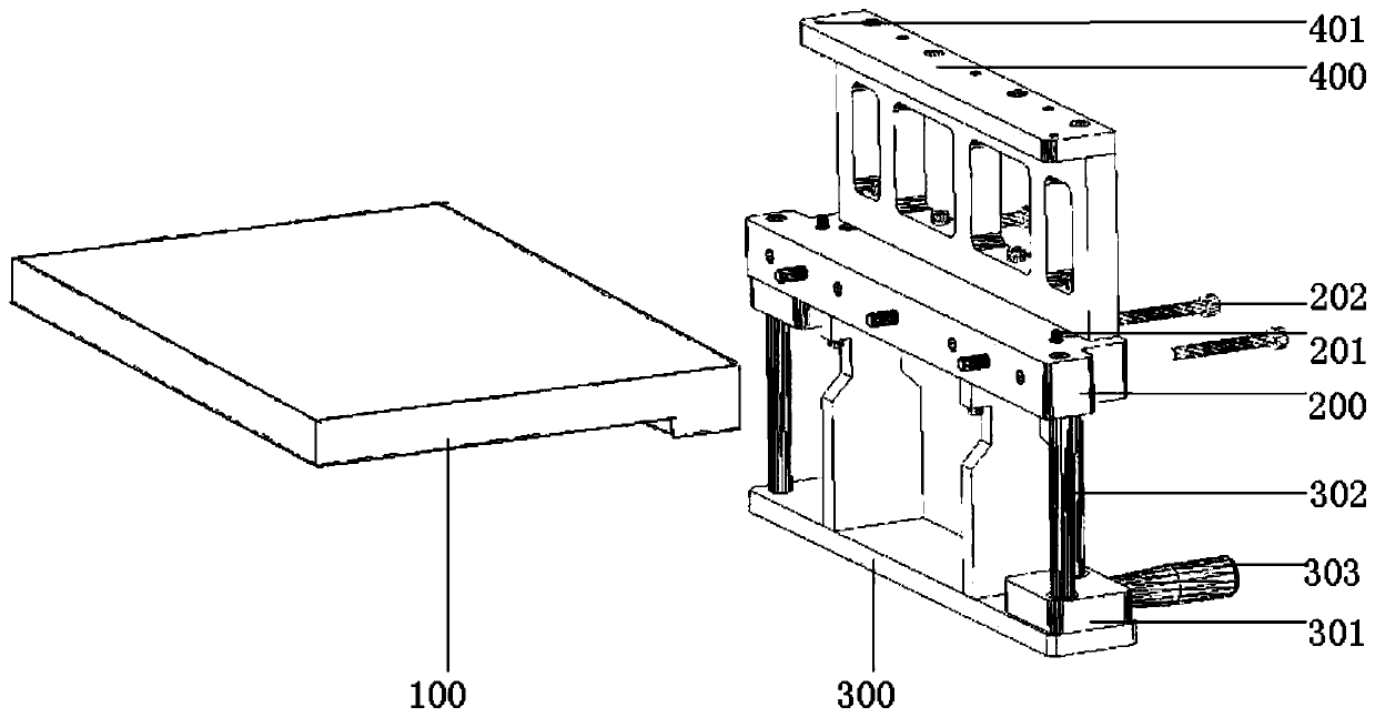
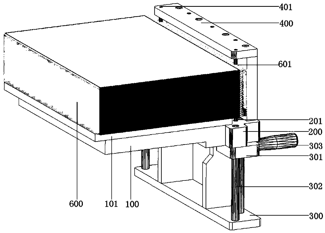
[0034] Attached below Figure 1-6 The technical solution of the present invention is described in detail with the embodiment, wherein: 100, support platform; 101, protective plate; 102, positioning groove; 200, operating platform; Support platform; 301, lifting platform; 302, guide rod; 303, operating handle; 400, correction platform; 401, correction hole; 500, storage platform; 501, gravity piece; 600, product;

[0035] Polishing Fixtures

[0036] In the first embodiment, the present invention provides a polishing fixing device, which can fix sheet-shaped products to be polished with positioning holes together, and then polish the products by polishing equipment.

[0037] like figure 1 As shown, it is a three-dimensional schematic view of the polishing fixture provided by the first embodiment of the present invention, including a support table 100, and an operation table 200 detachably and fixedly connected with the support table 100. The operation table 200 is provided wi...


PUM


Abstract

The invention discloses a polishing system and a polishing method. The polishing system comprises a polishing fixing device and polishing equipment, and can polish to-be-polished sheet-like products which are stacked together, and positioning holes used for positioning are formed in each to-be-polished product. The invention aims to provide the polishing system and the polishing method. After hundreds of products are fixed by the polishing fixing device of the polishing system, hundreds of products can be polished at a time by the polishing equipment, the rejection rate of the polished products is substantially reduced while polishing efficiency is increased, and the rejection rate is as low as about 0.3%.

Description

technical field [0001] The invention relates to the field of polishing, in particular to a polishing system and a polishing method. Background technique [0002] The production process of the light guide plate: the substrate (usually optical grade acrylic or PC sheet) is cut into a fixed size, and then the cut substrate is polished to a precise size, and finally on the bottom surface of the substrate Use laser engraving, V-shaped cross grid engraving, UV screen printing and other technologies to print the light guide dot structure. [0003] The traditional polishing technology is to directly stack the base materials of the light guide plate to be polished, and fix them with a baffle for processing. Because the base material of the light guide plate is provided with a boss with a height of about 1 mm, such as image 3 As shown, the base material of the stacked light guide plate is easy to tilt, so that only a small amount of products can be processed each time, and due to the...

Claims


Application Information

Patent Timeline
IPC IPC(8): B24B29/06B24B41/06
CPCB24B29/06B24B41/068
Inventor 方宗豹张恒霍乐毅李云周何钊陈林森
Owner NICROTEK
Why Eureka
Try Eureka