Complex electronic system fault diagnosis method based on fault propagation network

A fault propagation and electronic system technology, applied in the direction of detecting faulty hardware using a fault dictionary, detecting faulty computer hardware, generating response errors, etc., can solve problems such as difficult signal processing, complex physical cross-linking, and large system scale , to achieve the effect of improving fault diagnosis ability, complex physical cross-linking, and accurate identification and positioning

Active Publication Date: 2020-07-24
XIJING UNIV
View PDF3 Cites 4 Cited by
  • Summary
  • Abstract
  • Description
  • Claims
  • Application Information

AI Technical Summary

Problems solved by technology

[0010] The second is the problem of mutual influence of complex system test point signals
In order to improve the maintenance efficiency of complex systems, test points are usually set in limited positions of the system. The measurable signals (such as frequency, amplitude, etc.) of the test points come from multiple devices and are easily affected by factors such as the environment and electromagnetic interference. Difficult to handle
The method based on signal processing identifies a single fault based on the change of the measurable signal, and does not consider the interaction of signals when multiple faults occur, which limits the application of this method in complex systems
[0011] The third is the difficulty of obtaining complex system working condition data
However, the use of these methods requires the support of the actual operating status of the system and fau

Method used


Image

  • Complex electronic system fault diagnosis method based on fault propagation network
  • Complex electronic system fault diagnosis method based on fault propagation network
  • Complex electronic system fault diagnosis method based on fault propagation network

Examples


Embodiment Construction

[0056] The present invention will be described in further detail below in conjunction with specific examples, but not as a limitation of the present invention.

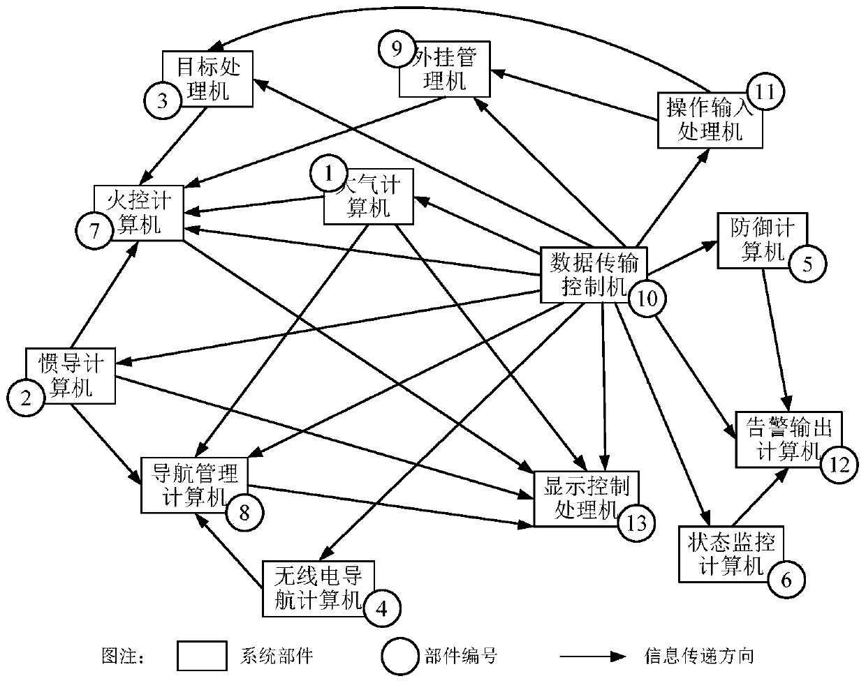
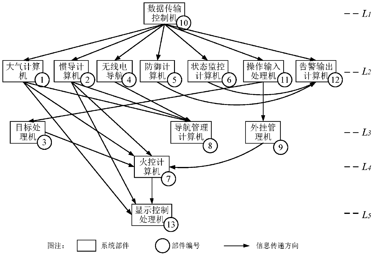
[0057] The present invention takes the integrated avionics system as an example to illustrate the implementation method of fault diagnosis. The integrated avionics system is an important part of a combat aircraft and mainly completes functions such as communication, navigation, weapon control, self-defense, and display control. The composition of the integrated avionics system As shown in Table 1.

[0058] Table 1 The names and serial numbers of the components of the integrated avionics system of the present invention

[0059]

[0060]

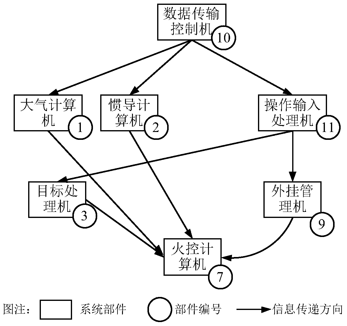
[0061] The fire control computer is the most complex part of the information interaction in the integrated avionics system. It receives data from the atmospheric computer, inertial navigation computer, target processor, external management machine and other components, performs ...


PUM


Abstract

The invention discloses a complex electronic system fault diagnosis method based on a fault propagation network, and the method comprises the steps: building a fault propagation directed graph of a complex electronic system through employing a graph theory, and achieving the storage and hierarchical optimization of the fault propagation directed graph through employing a matrix theory; simplifyingthe fault propagation network according to the fault phenomenon nodes; establishing a candidate fault source set by calculating the information output intensity and the working intensity of the nodes; and finally, calculating the comprehensive influence degree of the fault source by using an entropy weight method so as to determine a fault source therefrom. According to the invention, a fault propagation network is established based on a physical structure of a complex electronic system; the modeling problem of fault diagnosis of a complex electronic system is solved; design indexes such as the information output quantity and the fault-free working time of system components are utilized to solve the quantification problem of the system fault propagation influence relation, meanwhile, dependence on fault historical data is avoided, a fault source can be rapidly recognized and positioned, and the fault diagnosis capacity of a complex electronic system is improved.

Description

technical field [0001] The invention relates to the technical field of fault diagnosis of complex electronic systems, in particular to a fault diagnosis method for complex electronic systems based on a fault propagation network. Background technique [0002] A complex electronic system is a whole composed of multiple components (computers or electronic devices with computing power). When a component fails, the error information of the faulty component is often transmitted to one or more other components along the physical connection path. Information will be accumulated and amplified, causing other components to fail to work properly, which will cause a cascading effect of failures and ultimately affect the overall performance of the system. [0003] Due to the changing working environment and complex physical connection relationship, the main reason why a component in the system cannot work normally is caused by its own failure, such as hardware disconnection, short circuit...

Claims


Application Information

Patent Timeline
IPC IPC(8): G06F11/07G06F11/22
CPCG06F11/0748G06F11/2252Y04S10/52
Inventor 丛伟李鸿艳何苹
Owner XIJING UNIV
Why Eureka
Try Eureka