
High-precision silver-copper rod semi-continuous casting equipment with stirring and vibration device

A stirring vibration and semi-continuous casting technology, which is applied in the field of semi-continuous casting pouring flow control devices, can solve the problems of violent tumbling of molten metal, increase the depth of liquid caves, and reduce casting speed, so as to reduce labor costs, improve production efficiency, reduce The effect of casting segregation

Inactive Publication Date: 2020-07-28
江苏环胜合金科技有限公司
View PDF8 Cites 0 Cited by
  • Summary
  • Abstract
  • Description
  • Claims
  • Application Information

AI Technical Summary

Problems solved by technology

The shortcoming of this technique is: (1) the burning loss of silver is serious
Single-pipe centralized flow makes the high-temperature molten metal rush directly to the center of the mold to increase the depth of the liquid cavity, and the center of the ingot is prone to various shrinkage defects. In order to ensure product quality, the casting speed has to be reduced; the molten metal rushes directly to the center of the mold, causing the molten metal to churn Severe, easy to entrain slag

Method used


Image

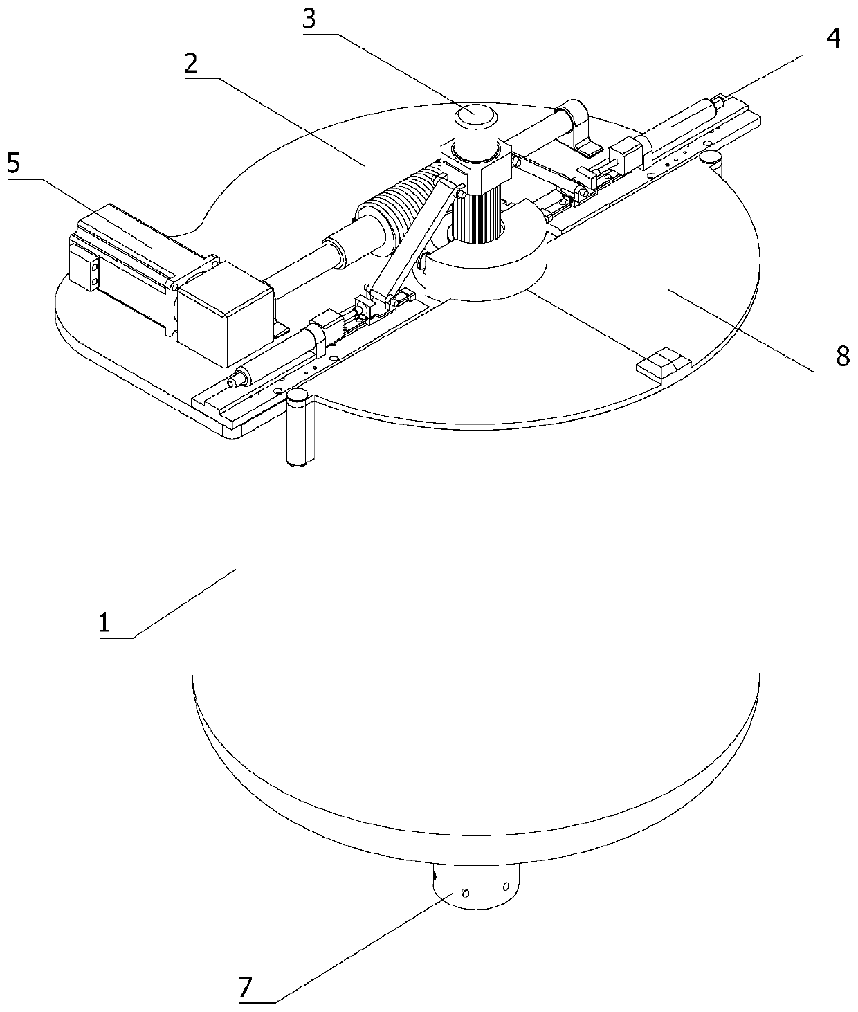
  • High-precision silver-copper rod semi-continuous casting equipment with stirring and vibration device
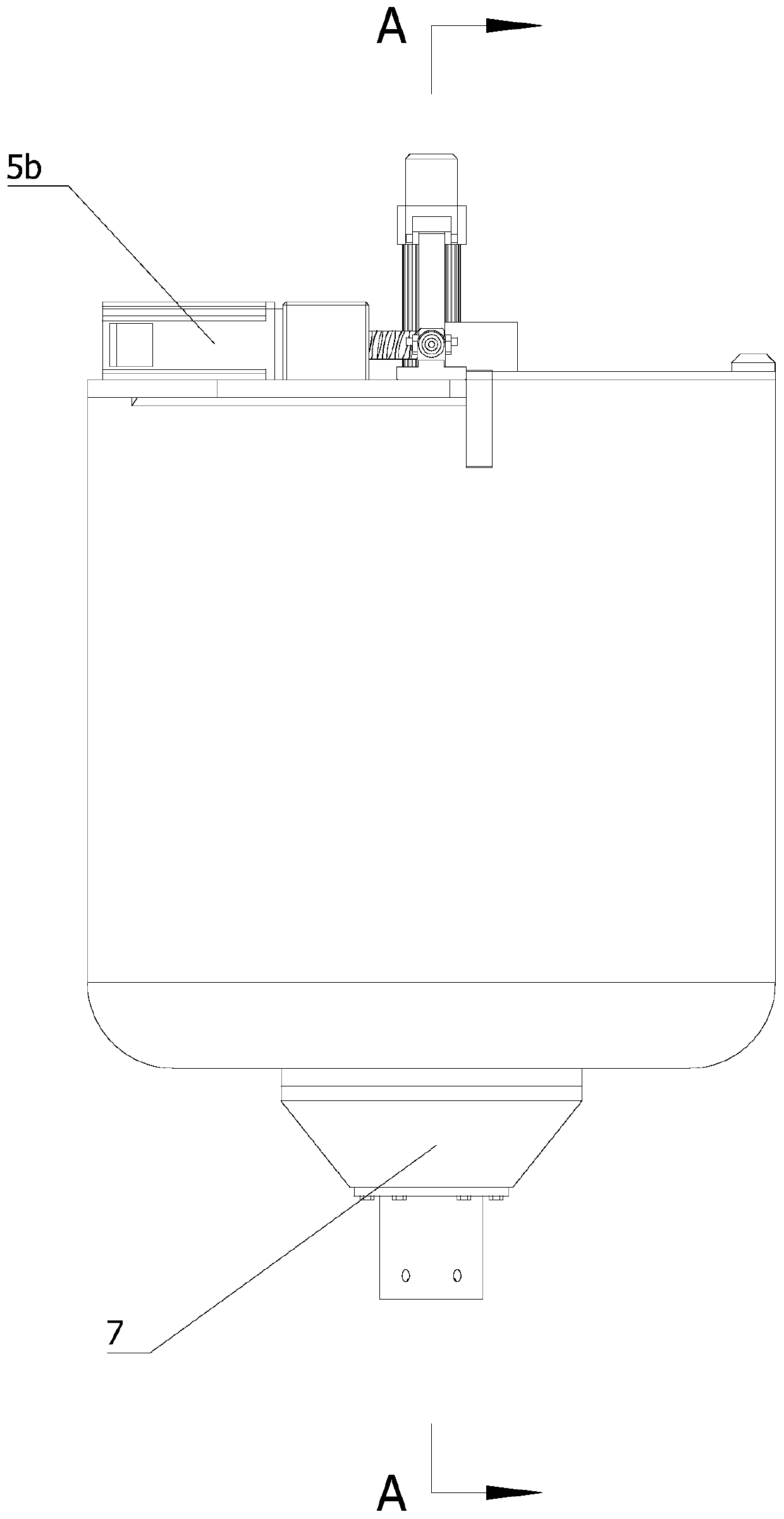
  • High-precision silver-copper rod semi-continuous casting equipment with stirring and vibration device
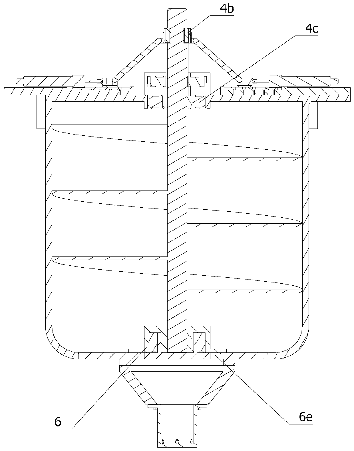
  • High-precision silver-copper rod semi-continuous casting equipment with stirring and vibration device

Examples


Embodiment Construction

[0041] In order to make the object, technical solution and advantages of the present invention clearer, the present invention will be further described in detail below in conjunction with the accompanying drawings and embodiments. It should be understood that the specific embodiments described here are only used to explain the present invention, not to limit the present invention.

[0042] In the description of the present invention, it should be noted that the terms "center", "upper", "lower", "left", "right", "front", "rear", "vertical", "horizontal", The orientation or positional relationship indicated by "inner", "outer", etc. is based on the orientation or positional relationship shown in the drawings, and is only for the convenience of describing the present invention and simplifying the description, rather than indicating or implying that the referred device or element must have Certain orientations, constructed and operative in certain orientations, therefore are not t...


PUM


Abstract

The invention relates to the technical field of a semi-continuous casting flow control device, in particular to high-precision silver-copper rod semi-continuous casting equipment with a stirring and vibration device. The equipment comprises a semi-continuous casting tundish, an end fixed frame, a rotating shaft, a lifting mechanism, a rotating mechanism, a flow adjusting mechanism, a graphite sleeve part, a top cover and a controller. The end fixed frame is mounted on the semi-continuous casting tundish. The rotating shaft is rotationally mounted on the end fixed frame. The lifting mechanism and the rotating mechanism are mounted on the end fixed frame. The output end of the lifting mechanism and the upper end of the rotating shaft are connected in a clamped manner. The output end of the rotating mechanism is engaged with the peripheral wall of the lifting mechanism. The work end of the rotating mechanism is arranged on the peripheral wall of the rotating shaft along the axis of the rotating shaft. The flow adjusting mechanism is mounted at the bottom of the semi-continuous casting tundish. The graphite sleeve part is mounted at the bottom end of the semi-continuous casting tundishand communicates with the interiorof the semi-continuous casting tundish. The top cover is arranged at the upper end f the semi-continuous casting tundish in a manner of being capable of being openedand closed. By means of the scheme, the property of forming materials is more excellent, the manual cost is reduced, and production efficiency is improved.

Description

technical field [0001] The invention relates to the technical field of semi-continuous casting pouring flow control devices, in particular to semi-continuous casting equipment for high-precision silver-copper rods with a stirring and vibrating device. Background technique [0002] The production of silver-copper rods in the semi-casting industry was originally a primary smelting process in which silver was directly put into copper liquid. The shortcoming of this technique is: (1) the burning loss of silver is serious. Putting the silver into the copper liquid at 0.25, the silver content of the silver-copper alloy produced can only reach about 0.08%, and about 60% of the silver is lost by oxidation and burning; (2) the silver-copper alloy ingot is severely segregated; The tensile strength and hardness of silver-copper alloy profiles are lower than the standard requirements. After adopting the secondary smelting process of silver-copper intermediate alloy, the silver content...

Claims


Application Information

Patent Timeline
IPC IPC(8): B22D11/114B22D11/18B22D11/103
CPCB22D11/004B22D11/103B22D11/114B22D11/18
Inventor 仇文秋
Owner 江苏环胜合金科技有限公司
Learn More