Coated cutting tool

A cutting tool and coating technology, applied in the direction of manufacturing tools, workpieces, drilling tool accessories, etc., can solve problems such as inability to extend tool life

Active Publication Date: 2020-07-28
TUNGALOY CORP
View PDF13 Cites 0 Cited by
  • Summary
  • Abstract
  • Description
  • Claims
  • Application Information

AI Technical Summary

Problems solved by technology

Therefore, there is a problem that the life of the tool cannot be extended due to this

Method used


Image

  • Coated cutting tool
  • Coated cutting tool
  • Coated cutting tool

Examples


Embodiment

[0098] Hereinafter, the present invention will be described in more detail with reference to examples, but the present invention is not limited to these examples.

[0099] As a substrate, prepare a CNMG120412 shape with 88.9WC-7.9Co-1.5Ti N-1.4NbC-0.3Cr 3 C 2 Cemented carbide cutting inserts having a composition of (above is mass %) and having a shape of CN MG120412 and having 89.7WC-7.1Co-1.5TiN-1.5NbC-0.2Cr 3 C 2 (The above is the mass %) cutting insert made of cemented carbide. After performing fillet honing on the edge portion of the base material with a SiC brush, the surface of the base material was cleaned.

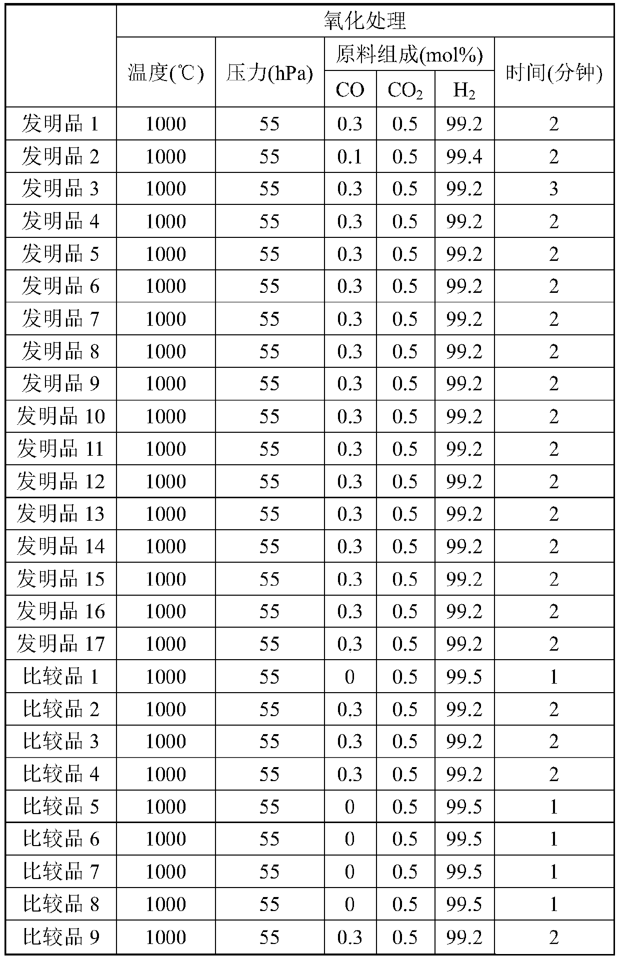
[0100] [Invention products 1-17 and comparative products 1-9]

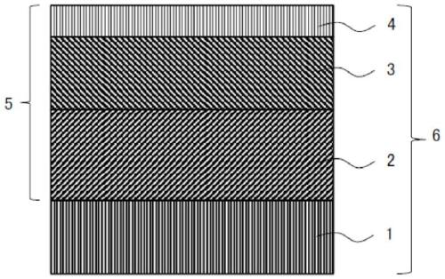
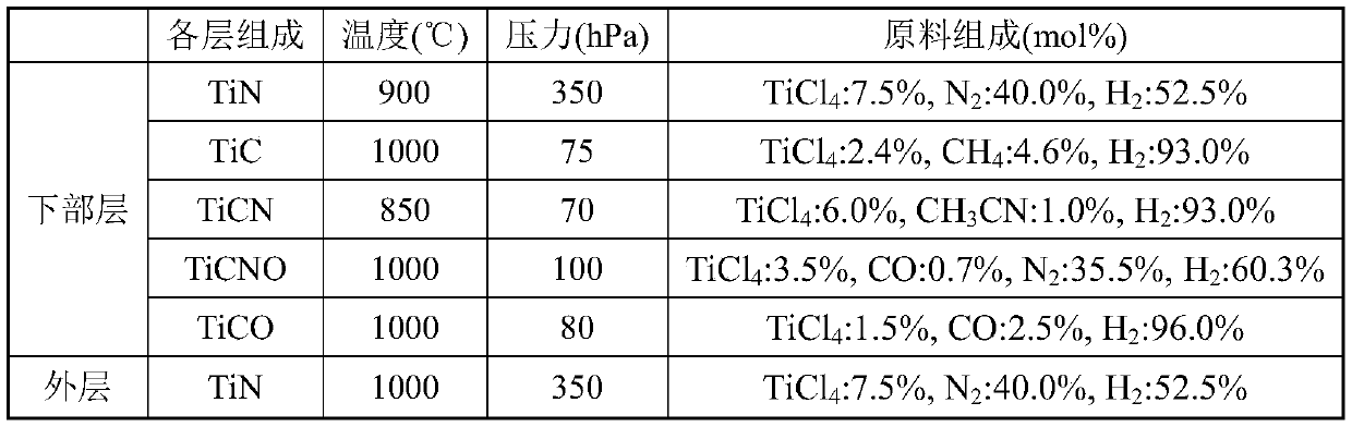
[0101] After cleaning the surface of the substrate, a coating layer is formed by chemical vapor deposition. First, put the substrate into an external thermal chemical vapor deposition device, and form the composition shown in Table 6 on the surface of the substrate with the average thickness shown...


PUM


Abstract

A coated cutting tool comprising a substrate and a coating layer formed on a surface of the substrate, wherein: the coating layer comprises a lower layer, an intermediate layer, and an upper layer inthis order from the substrate side; the lower layer comprises one or two or more Ti compound layers containing a Ti compound of Ti and an element of at least one kind selected from the group consisting of C, N, O and B, the intermediate layer comprises an alpha-Al2O3 layer containing alpha-Al2O3, and the upper layer comprises a TiCNO layer containing TiCNO; an average thickness of the coating layer is 5.0 microns or more and 30.0 microns or less; in a specific first cross section, a misorientation A satisfies a specific condition; and in a specific second cross section, a misorientation B satisfies a specific condition.

Description

technical field [0001] The present invention relates to a coated cutting tool. Background technique [0002] Conventionally, it is widely known that a coated cutting tool obtained by vapor-depositing a coating layer on the surface of a substrate made of cemented carbide with a total film thickness of 3 to 20 μm by chemical vapor deposition is used for cutting steel, cast iron, etc. . As the above-mentioned coating layer, for example, there are known carbides, nitrides, carbonitrides, carbon oxides and carbonitrides selected from Ti and aluminum oxide (Al 2 o 3 ) in the group consisting of a single layer or a coating layer formed of two or more layers. [0003] In Patent Document 1, a surface-coated cutting tool is described, which is characterized in that, on the surface of a tool base made of tungsten carbide-based cemented carbide, a lower layer made of a titanium compound layer and an aluminum oxide layer ( Al 2 o 3 layer) formed as a hard coating layer, in this sur...

Claims


Application Information

Patent Timeline
IPC IPC(8): C23C16/30C23C16/40B23B27/14B23B51/00B23C5/16
CPCC23C16/30C23C16/403B23B27/14B23B51/00B23C5/16B23B2228/04B23B2228/10B23B2228/36C23C16/36C23C16/34C23C28/044C23C16/38C23C30/005B23B27/148C23C16/308B23B2228/105C23C16/32
Inventor 高桥欣也福岛直幸
Owner TUNGALOY CORP
Why Eureka
Try Eureka