Centrifugal extractor for solid-liquid phase system

A centrifugal extraction machine, solid-liquid phase technology, applied in the direction of centrifuge, liquid solution solvent extraction, solvent extraction, etc., can solve the problems of structural parameter change, no removal, production interruption, etc., and achieve the effect of compact structure

Active Publication Date: 2020-07-31
HEFEI GENERAL MACHINERY RES INST +1
View PDF6 Cites 4 Cited by
  • Summary
  • Abstract
  • Description
  • Claims
  • Application Information

AI Technical Summary

Problems solved by technology

The problem with the above-mentioned centrifugal extractors that are commonly used at present is that there is no design for removing solids in the liquid phase material in the traditional structure. Therefore, if the material contains solids in a certain liquid phase due to upstream processes, the solids will be removed after entering the extractor. , will gradually deposit under the action of centrifugal force
Generally, the density of solids is greater than that of the liquid phase, so these solids will deposit on the inner surface of the rotor separation chamber, which will lead to the following problems: 1) With the increase of deposited solids, the dynamic balance of the rotor will be destroyed, resulting in abnormal vibration of the equipment, resulting in Hidden safety hazards such as internal structure collisions; 2) leading to changes in the internal structural parameters of the extractor equipment, such as smaller inner diameters of drums, narrower flow channels, etc., and even blockage of flow channels
However, the internal flow path of the centrifugal extractor is complicated, and regular cleaning requires the disassembly of the machine, which consumes manpower and material resources, and causes production interruption; frequent disassembly and assembly will also cause problems such as wear of the joints of related components and failure of seals
At the same time, it is easy to leave dead angles in the complex flow channel, which is difficult to remove

Method used


Image

  • Centrifugal extractor for solid-liquid phase system
  • Centrifugal extractor for solid-liquid phase system
  • Centrifugal extractor for solid-liquid phase system

Examples


Embodiment Construction

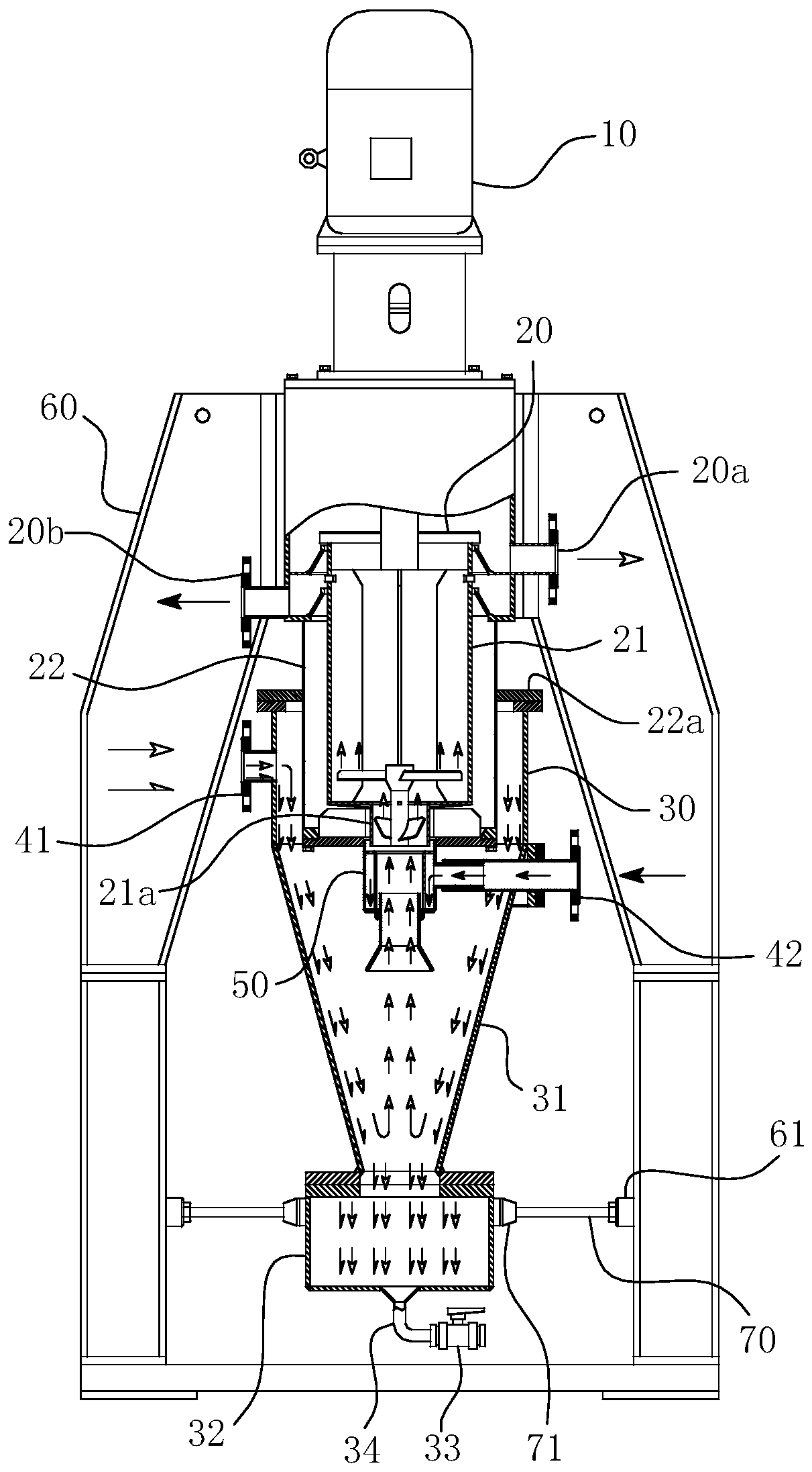
[0041] For ease of understanding, here the concrete structure of the present invention and working method are further described as follows:

[0042] The main part of the centrifugal extractor of the present invention, that is, the centrifugal extraction part 20, still follows the structure of the traditional centrifugal extractor. That is to say, it includes a power source 10, a rotating drum 21, an outer casing 22 sleeved on the outer wall of the rotating drum 21, a frame 60, and the like. The power source 10 is the power source of the present invention as the centrifugal extraction process, generally provides rotational power for the power motor, and then the power motor and the rotating drum 21 are connected by a shaft coupling. Frame 60 supports the power source 10, rotating drum 21 and outer shell 22 etc. of centrifugal extractor, is the support part of whole equipment weight, and frame 60 requires sufficient rigidity. Drum 21 is arranged such as light and heavy weir pla...


PUM


Abstract

The invention relates to the technical field of centrifugal extraction, in particular to a centrifugal extractor for a solid-liquid phase system. The centrifugal extractor comprises a power source, acentrifugal extraction part, a feeding port, a heavy phase discharging port, a light phase discharging port and a settling separation assembly, the settling separation assembly comprises a separationcylinder, and the feeding port of the centrifugal extraction part vertically extends downwards and is coaxially arranged in a cylinder cavity of the separation cylinder. The appearance of the cylindercavity of the separation cylinder is of a conical structure with a thick upper portion and a thin lower portion, a solid-phase medium outlet is formed in the bottom of the separation cylinder, a solid-phase containing liquid phase feeding pipe allowing a solid-phase containing liquid phase to enter the cylinder cavity is arranged on the cylinder wall of the separation cylinder, and the feeding direction of the solid-phase containing liquid phase feeding pipe is tangent to the cylinder cavity wall. The centrifugal extractor further comprises a light-phase feeding pipe, which is communicated with the feeding port and can allow a to-be-mixed liquid-phase medium to enter the cylinder cavity. The solids in a liquid phase can be actively and effectively removed by the centrifugal extractor, a clear heavy phase liquid is obtained, and finally, the reliability, continuity and stability of the whole centrifugal extraction process are greatly improved.

Description

technical field [0001] The invention relates to the technical field of centrifugal extraction, in particular to a centrifugal extractor for a solid-liquid phase system. Background technique [0002] Centrifugal extractor is a high-efficiency liquid-liquid extraction equipment designed based on the principle of extraction and separation. The stirring and mixing of the rotor system of the centrifugal extractor and the sedimentation and separation of the separation chamber achieve the purpose of extraction, so it is widely used in hydrometallurgy, medicine, fine chemical industry and other fields. The traditional centrifugal extractor is described in the publication number "CN202638043U" and the publication number "CN202638044U". Orifice, the axial heavy phase diversion hole is formed between the side of the partition and the inner wall of the diversion body, the heavy phase weir is arranged above the diversion body, and the material inlet, heavy phase outlet and light phase o...

Claims


Application Information

Patent Timeline
Patent Type & Authority Applications(China)
IPC IPC(8): B01D11/04B04B5/10B04B11/04
CPCB01D11/04B01D11/0446B01D11/048B04B5/10B04B11/04
Inventor 陈崔龙张德友朱碧肖丁建国邓超刘呈启
Owner HEFEI GENERAL MACHINERY RES INST
Why Eureka
Try Eureka