Pipe fitting machining device for electromechanical machining and machining method of pipe fitting machining device
A technology for processing devices and pipe fittings, which is applied to metal processing mechanical parts, positioning devices, clamping devices, etc., can solve the problems of excessive use of manpower and single setting mode of punching devices, and achieves the adaptability of lifting devices and easy fixing. Effect
- Summary
- Abstract
- Description
- Claims
- Application Information
AI Technical Summary
Problems solved by technology
Method used
Image
Examples
Embodiment 1
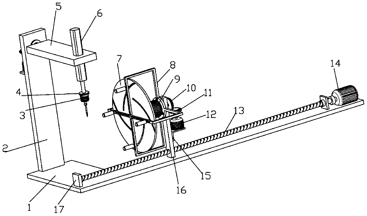
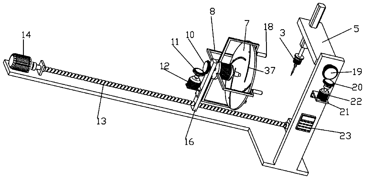
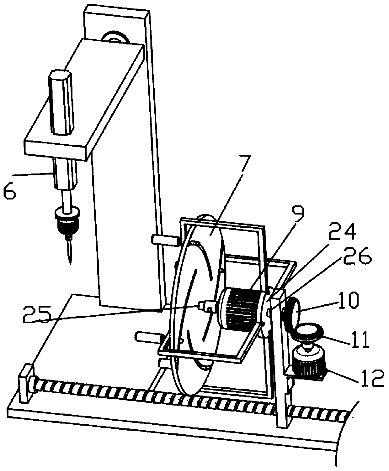
[0042] Such as Figure 1-8 Shown is a pipe fitting processing device for electromechanical processing, including an L-shaped base plate 1, an electric push rod 6, a drive motor 14 and a slide plate 16, and the top of the L-shaped base plate 1 is fixedly connected with a straight plate 2, a drive motor 14 and a straight block 17. The output end of the motor 14 is fixedly connected with a threaded rod 13, and the straight block 17 is rotatably connected with the threaded rod 13 through a fixedly connected bearing, and the threaded rod 13 is fixedly connected with the inner ring of the bearing, and the straight block 17 is fixedly connected with the outer ring of the bearing, The threaded rod 13 is threadedly connected with a slide plate 16 that is fitted and slidably connected with the L-shaped bottom plate 1. The drive motor 14 drives the threaded rod 13 to rotate, and the threaded rod 13 drives the slide plate 16 to move. The slide plate 16 drives the pipe fitting clamped by th...
Embodiment 2
[0045] Embodiment 2 is a further improvement to Embodiment 1.
[0046] Such as Figure 1-8 As shown, the disc 24 is connected with a clamping structure used for pipes with different diameters, and the clamping structure includes a rotating disc 7, a U-shaped plate 8, a first rotating motor 9, a sliding rod 28, a sliding block 31 and a round rod 34, The first rotating motor 9 is fixedly installed on the left side of the disc 24, and the output end of the first rotating motor 9 is fixedly connected with the first rotating rod 25, and the left end of the first rotating rod 25 is fixedly connected with the rotating disc 7, and on the rotating disc 7 An arc-shaped groove 37 is evenly opened along the circumferential direction, and the U-shaped plate 8 is evenly arranged on the outer edge of the disc 24 along the circumferential direction. A slider 31 is slidingly connected, and the two ends of the top of the slider 31 are placed with a limit slider 33 for the lateral limit of the ...
Embodiment 3
[0049] Embodiment 3 is a further improvement to Embodiment 1.
[0050] Such as Figure 1-8 The outer wall of the shown straight plate 2 is connected with an angle adjustment structure and a controller 23 for drilling angle adjustment, and the angle adjustment structure includes a third bevel gear 19, a fourth bevel gear 20, a third rotating motor 22 and a third rotating rod 36, The straight plate 2 is fixedly connected with a second support plate 21, the third rotating motor 22 is fixedly installed on the second support plate 21, the top of the output end of the third rotating motor 22 is fixedly connected with a fourth bevel gear 20, the fourth bevel gear 20 The third bevel gear 19 is meshingly connected, and the third bevel gear 19 is fixedly connected with a third rotating rod 36. The top of the straight plate 2 is rotationally connected with the third rotating rod 36 through a fixedly connected bearing, and the front end of the third rotating rod 36 is connected to the hor...
PUM
 Abstract
Description
Claims
Application Information
 - R&D
- Intellectual Property
- Life Sciences
- Materials
- Tech Scout
- Unparalleled Data Quality
- Higher Quality Content
- 60% Fewer Hallucinations
Browse by: Latest US Patents, China's latest patents, Technical Efficacy Thesaurus, Application Domain, Technology Topic, Popular Technical Reports.
© 2025 PatSnap. All rights reserved.Legal|Privacy policy|Modern Slavery Act Transparency Statement|Sitemap|About US| Contact US: help@patsnap.com


