Carton cutting device and cutting method

A cutting device and carton technology, applied in welding/welding/cutting items, packaging, papermaking, etc., can solve problems such as burrs and affect product quality, and achieve the effect of improving convenience and cutting quality

Active Publication Date: 2020-07-31
广州市三隆泰纸业有限公司
View PDF5 Cites 3 Cited by
  • Summary
  • Abstract
  • Description
  • Claims
  • Application Information

AI Technical Summary

Problems solved by technology

However, during the cutting, cutting and returning process of the cutting knife, due to the friction between the cutting knife and the cutting surface of the cardboard, the cutting knife will generate a certain pulling force on the cardboard, resulting in burrs at the cutting edge of the paper, which will affect the quality of the product. , therefore, it is necessary to improve the

Method used


Image

  • Carton cutting device and cutting method
  • Carton cutting device and cutting method
  • Carton cutting device and cutting method

Examples


Embodiment 1

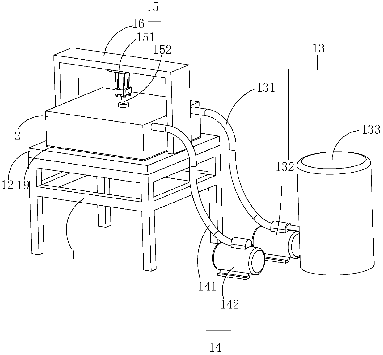
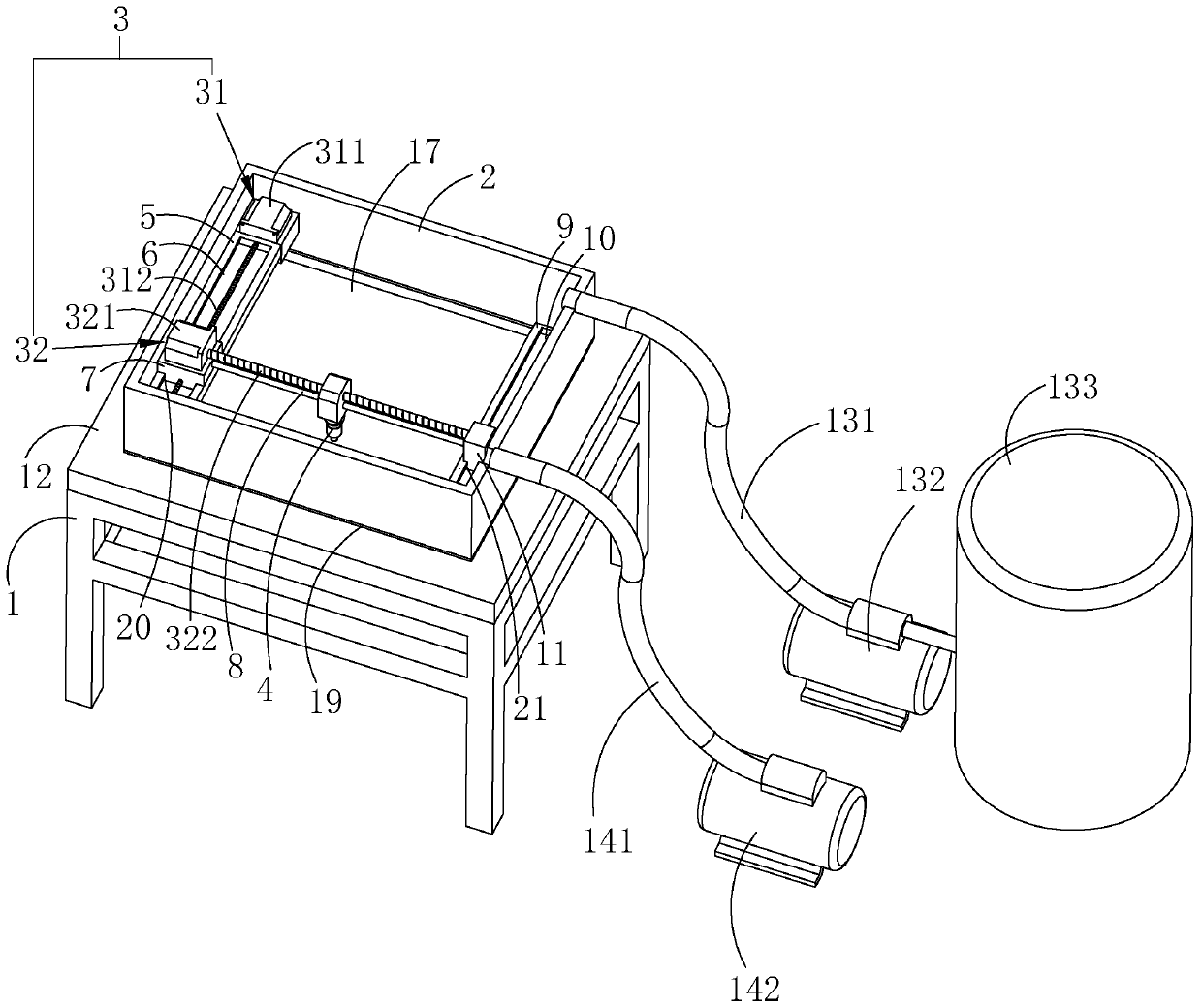
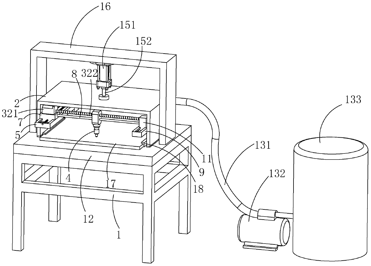
[0039] refer to figure 1 , is a kind of carton cutting device disclosed by the present invention, comprising a mounting frame 1 and a worktable 12 installed on the mounting frame 1, a sealing box 2 is arranged on the working table 12, one end of the sealing box 2 is open, and the opening of the sealing box 2 is The end faces the workbench 12, and the open end of the sealing box 2 is sealed and connected with the workbench 12. One side of the installation frame 1 is provided with a ventilation assembly 13. The ventilation assembly 13 communicates with the sealing box 2. The ventilation assembly 13 stores There are inert gases.

[0040] The ventilation assembly 13 includes a soft ventilation pipe 131, an air suction pump 132 and an air storage box 133. The air storage box 133 and the air suction pump 132 are all placed on the ground. The air tank 133 communicates with the air pump 132 . Specifically, the air outlet end of the air pump 132 communicates with the air pipe 131 , a...

Embodiment 2

[0068] refer to figure 1 , is a kind of carton cutting method disclosed in the present invention, and this method is realized by adopting the cutting device of embodiment 1, comprises the following steps:

[0069] S1: Put the cardboard 17 to be cut on the workbench 12, and start the air cylinder 15 so that the cardboard 17 is sealed and placed between the sealed box 2 and the workbench 12;

[0070] S2: Start the exhaust fan 142 to extract the original gas between the sealed box 2 and the workbench 12, and then send the gas in the gas storage box 133 into the space between the sealed box 2 and the workbench 12 through the air pump 132 cavity;

[0071] S3: start the laser component;

[0072] S4: Start the air cylinder 15 to drive the sealing box 2 to separate from the workbench 12 .

[0073] The implementation principle of this embodiment is:

[0074] By sealing the cardboard 17 between the sealed box 2 and the workbench 12, filling the sealed box 2 with helium after vacuumi...


PUM


Abstract

The invention relates to the technical field of cutting machines. In order to solve the problem that burrs are generated on a cut surface of a paperboard when the paperboard is cut, the invention provides a carton cutting device. The carton cutting device comprises a mounting rack and a worktable mounted on the mounting rack. A sealing box is arranged on the worktable, a lifting assembly is mounted on the mounting rack, a laser assembly is arranged in the sealing box, a laser driving assembly is mounted in the sealing box, and a ventilating assembly and a vacuumizing assembly are arranged on one side of the mounting rack. By way of laser cutting, when the laser assembly cuts a carton, the laser assembly with a cutting knife function is not in direct contact with the paperboard, so that theburrs are hardly generated on the cut surface of the paperboard, and therefore, the cutting quality of the paperboard is improved. By inflating inert gas into a sealing cover, the inert gas is gas which is not prone to oxidize, so that when the paperboard is cut, local burning hardly happens at a cutting position. The paperboard is not prone to be carbonized locally, so that the cutting effect ofthe paperboard is relatively excellent.

Description

technical field [0001] The invention relates to the technical field of cutting machines, in particular to a carton cutting device and a cutting method. Background technique [0002] At present, before making cartons, it is necessary to cut the entire larger cardboard into the required style and size. The most primitive method is to adopt manual cutting, manually fix the cardboard on the workbench, and then use a cutting knife to cut. The cutting efficiency of this method is low, the cutting quality cannot be guaranteed, and manual operation has certain potential safety hazards. One way is to use an automatic paper cutting machine for cutting. The automatic paper cutting machine includes a cutting knife and a controller that controls the cutting knife to cut the paper. When the automatic paper cutting machine is cutting, the paper is placed on the workbench, and the controller controls the cutting. The knife cuts the paper on the workbench. However, during the cutting, cut...

Claims


Application Information

Patent Timeline
Patent Type & Authority Applications(China)
IPC IPC(8): B31B50/20B31B50/00B23K26/38B23K26/402B23K26/70B23K103/00
CPCB23K26/38B23K26/402B23K26/702B31B50/006B31B50/20B23K2103/40
Inventor 刘俊朱建平莫剑兴
Owner 广州市三隆泰纸业有限公司
Why Eureka
Try Eureka