
Photoetching machine motion track planning method and device, computer equipment and storage medium

A technology of motion trajectory and lithography machine, which is applied in the direction of photomechanical equipment, micro-lithography exposure equipment, photolithography process exposure device, etc., can solve the problem of large vibration amplitude, long convergence time, lithography machine movement precision and lithography precision. low level problem

Pending Publication Date: 2020-07-31
GOOGOL TECH SHENZHEN LTD GUANGDONG
View PDF4 Cites 4 Cited by
  • Summary
  • Abstract
  • Description
  • Claims
  • Application Information

AI Technical Summary

Problems solved by technology

However, after the lithography machine accelerates to the maximum speed according to the current trajectory, the vibration amplitude is large and the convergence time is long, resulting in low motion accuracy and lithography accuracy of the lithography machine.

Method used


Image

  • Photoetching machine motion track planning method and device, computer equipment and storage medium
  • Photoetching machine motion track planning method and device, computer equipment and storage medium
  • Photoetching machine motion track planning method and device, computer equipment and storage medium

Examples


Embodiment Construction

[0051] In order to make the purpose, technical solutions and advantages of the present application more clearly understood, the present application will be described in further detail below with reference to the accompanying drawings and embodiments. It should be understood that the specific embodiments described herein are only used to explain the present application, but not to limit the present application.

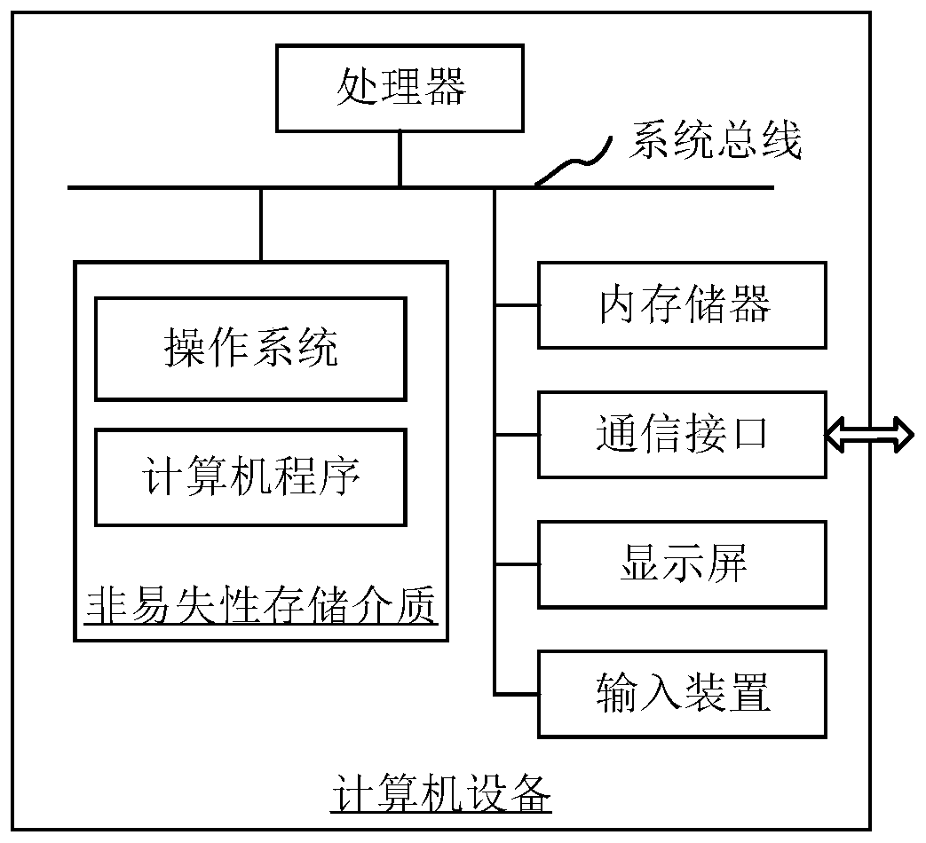
[0052] The lithography machine motion trajectory planning method provided in this application can be applied to such as figure 1 in the terminal shown. In one embodiment, a computer device is provided, the computer device may be a terminal, and its internal structure diagram may be as follows figure 1 shown. The computer equipment includes a processor, memory, a communication interface, a display screen, and an input device connected by a system bus. Among them, the processor of the computer device is used to provide computing and control capabilities. The memory o...


PUM


Abstract

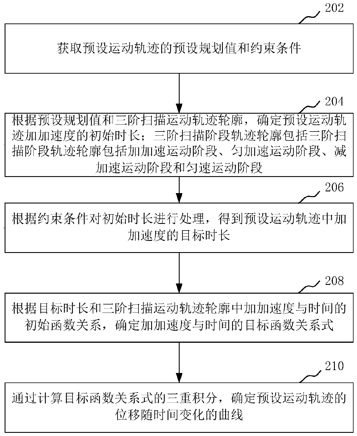
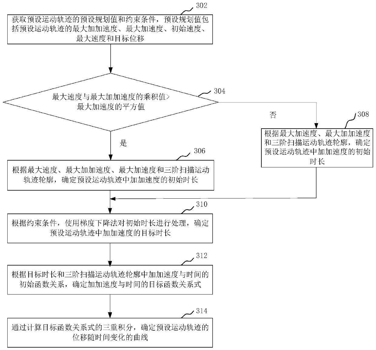
The invention relates to a photoetching machine motion trail planning method and device, computer equipment and a storage medium. The method comprises the steps: acquiring a preset planning value anda constraint condition of a preset motion trail; determining the initial duration of jerk in the preset motion trail according to the preset planning value and a third-order scanning motion trail contour, wherein the third-order scanning stage track contour comprises a jerk motion stage, a uniform acceleration motion stage, a reduced acceleration motion stage and a uniform motion stage; processingthe initial duration according to the constraint condition to obtain a target duration of jerk in the preset motion trail; determining a target function relational expression of jerk and time according to the target duration and the initial function relation of the jerk and the time in the third-order scanning motion track contour; and determining a time-varying curve of the displacement of the preset motion trail by calculating triple integrals of the objective function relational expression. By adopting the method, the motion precision and photoetching precision of the photoetching machinecan be improved.

Description

technical field [0001] The present application relates to the technical field of integrated circuits, in particular to a method, device, computer equipment and storage medium for planning a movement trajectory of a photolithography machine. Background technique [0002] With the increase of integrated circuit processing density and integration, the lithography machine table has higher and higher requirements for motion control accuracy, and the trajectory planning precision of the lithography machine directly determines the accuracy of motion control. During the photolithography process of the stepper lithography machine, the mask plate and the wafer are mounted on the reticle stage and the wafer stage respectively. When exposing, the mask and wafer move to the specified position, and the light source is turned on; after the light passes through the mask, it passes through the lens, which can reduce the circuit pattern to a quarter of its original size, and then project it o...

Claims


Application Information

Patent Timeline
IPC IPC(8): G03F7/20
CPCG03F7/705G03F7/70733
Inventor 贾松涛李猛
Owner GOOGOL TECH SHENZHEN LTD GUANGDONG
Learn More