Self-heat-dissipation system for switched reluctance motor

A switched reluctance motor, self-cooling technology, applied in electrical components, electromechanical devices, electric components, etc., can solve the problem that the switched reluctance motor cannot operate normally, the internal components of the switched reluctance motor are damaged, and affect the normal operation of the switched reluctance motor. Operation and other problems, to achieve the effect of convenient operation and start, preventing excessive temperature, and facilitating heat conduction and cooling

Inactive Publication Date: 2020-07-31
山东翔讯科技有限公司
View PDF0 Cites 8 Cited by
  • Summary
  • Abstract
  • Description
  • Claims
  • Application Information

AI Technical Summary

Problems solved by technology

[0004] In the prior art, the switched reluctance motor will generate a lot of heat during operation, and the heat will accumulate, which will easily affect the normal operation of the switched reluctance motor, and even cause damage to the internal components of the switched reluctance motor, resulting in The motor cannot be used normally, and the existing switched reluctance motor is only cooled by air through the cooling fan installed inside the rear cover. Numerically, for this purpose, a self-cooling system for switched reluctance motors is proposed

Method used


Image

  • Self-heat-dissipation system for switched reluctance motor
  • Self-heat-dissipation system for switched reluctance motor
  • Self-heat-dissipation system for switched reluctance motor

Examples


Embodiment Construction

[0025] The following will clearly and completely describe the technical solutions in the embodiments of the present invention with reference to the accompanying drawings in the embodiments of the present invention. Obviously, the described embodiments are only some, not all, embodiments of the present invention.

[0026] In describing the present invention, it should be understood that the terms "upper", "lower", "front", "rear", "left", "right", "top", "bottom", "inner", " The orientation or positional relationship indicated by "outside", etc. is based on the orientation or positional relationship shown in the drawings, and is only for the convenience of describing the present invention and simplifying the description, rather than indicating or implying that the referred device or element must have a specific orientation, so as to Specific orientation configurations and operations, therefore, are not to be construed as limitations on the invention.

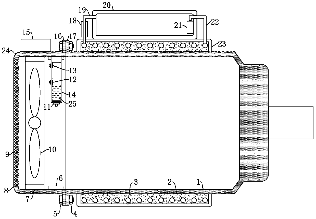
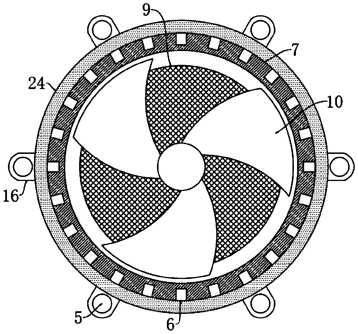
[0027] refer to Figure ...


PUM


Abstract

The invention discloses a self-heat-dissipation system for a switched reluctance motor. The self-heat-dissipation system comprises a switch reluctance motor shell, the switch reluctance motor shell issleeved with a fixing plate., the fixed plate is fixedly connected with the switched reluctance motor shell, a heat conduction plate is fixedly connected to the inner side of the fixed plate, a cooling pipeline is arranged in the heat conduction plate, a circulating water cooling mechanism communicated with the cooling pipeline is arranged on the outer side of the fixing plate, a rear cover shellis arranged at the rear end of the switched reluctance motor shell, the switched reluctance motor shell is detachably connected with the rear cover shell through a mounting mechanism, and a heat dissipation mechanism is arranged in the rear cover shell. The self-heat-dissipation system is reasonable in structural design, the purpose of circuit conduction is achieved through mercury rising along with temperature rising of the switched reluctance motor, the good heat dissipation effect of air cooling heat dissipation and water cooling heat dissipation is achieved, the temperature in the switched reluctance motor shell is prevented from being too high, and operation of the switched reluctance motor is facilitated.

Description

technical field [0001] The invention relates to the technical field of heat dissipation equipment for switched reluctance motors, in particular to a self-radiation system for switched reluctance motors. Background technique [0002] Switched reluctance motor is a type of speed regulating motor developed after DC motor and brushless DC motor. Has been widely used in household appliances, aviation, aerospace, electronics, machinery and electric vehicles and other fields. [0003] Switched reluctance motor is a new type of speed control motor, which is the latest generation of speed control system following frequency conversion speed control system and brushless DC motor speed control system. It has simple and firm structure, wide speed range and high system reliability. The complete system mainly consists of motor entity, power converter, controller and position detector. The controller contains the power converter and control circuit, while the rotor position detector is i...

Claims


Application Information

Patent Timeline
Patent Type & Authority Applications(China)
IPC IPC(8): H02K5/18H02K5/20H02K9/04H02K9/19
CPCH02K5/18H02K5/20H02K9/04H02K9/19
Inventor 王永进刘志宏赵剑青
Owner 山东翔讯科技有限公司
Why Eureka
Try Eureka