[0024] The present application is described in detail below, and examples of embodiments of the present application are shown in the drawings, wherein the same or similar reference numerals denote the same or similar components or components having the same or similar functions throughout. Also, detailed descriptions of known technologies will be omitted if they are not necessary to illustrate the features of the present application. The embodiments described below by referring to the figures are exemplary only for explaining the present application, and are not construed as limiting the present application.
[0025] Those skilled in the art can understand that, unless otherwise defined, all terms (including technical terms and scientific terms) used herein have the same meanings as commonly understood by those of ordinary skill in the art to which this application belongs. It should also be understood that terms, such as those defined in commonly used dictionaries, should be understood to have meanings consistent with their meaning in the context of the prior art, and unless specifically defined as herein, are not intended to be idealized or overly Formal meaning to explain.
[0026] The technical solution of the present application and how the technical solution of the present application solves the above technical problems will be described in detail below with specific embodiments.
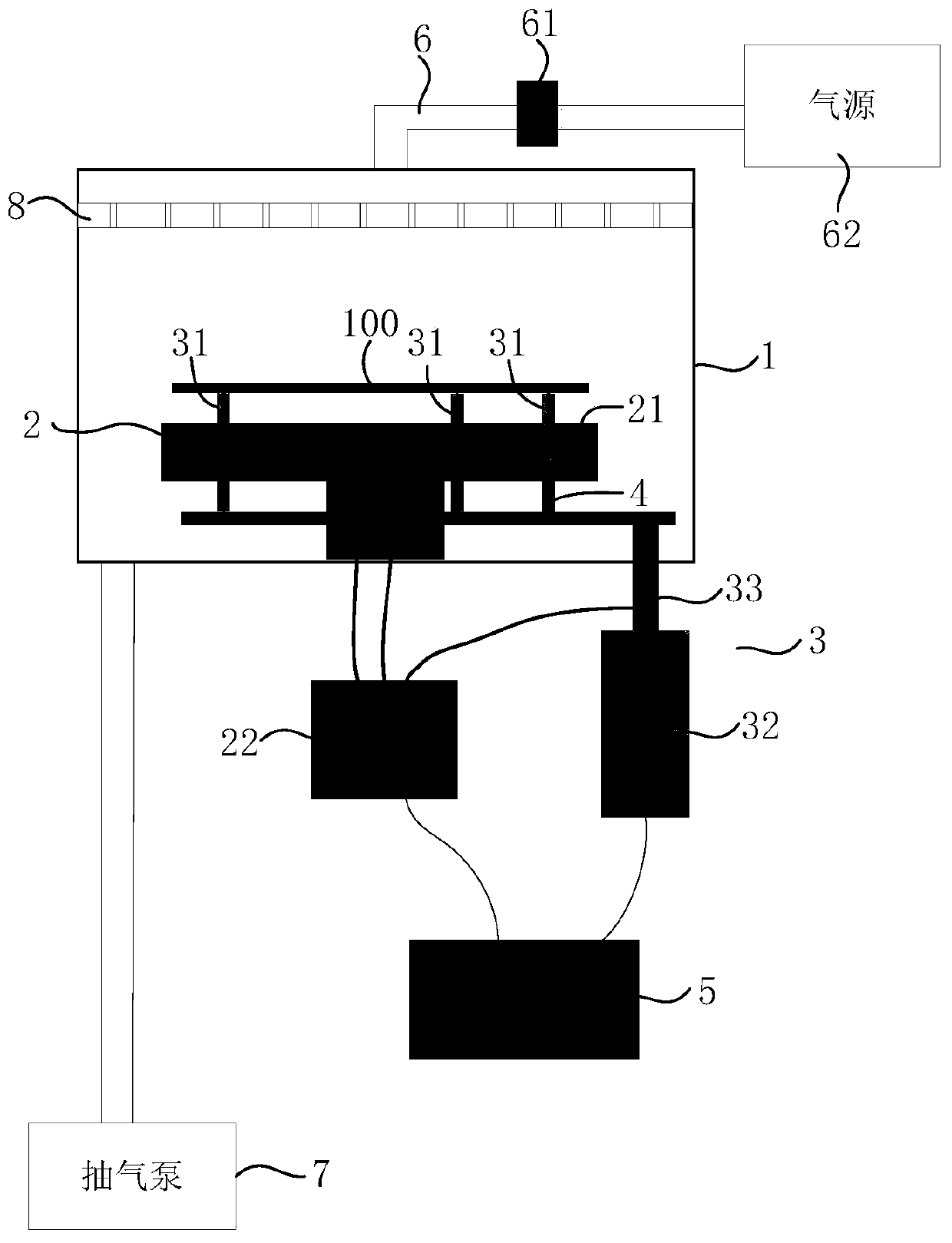
[0027] The embodiment of the present application provides a semiconductor processing equipment, the structure schematic diagram of the semiconductor processing equipment is as follows figure 1 As shown, it includes: a chamber 1, a lifting assembly 3, a base 2 and a temperature measuring assembly 4 arranged in the chamber 1; station; a plurality of stations correspond to a plurality of target temperatures one by one, and the distance from each station to the upper surface 21 of the base 2 is inversely proportional to the corresponding target temperature value; the temperature measuring assembly 4 is arranged between the lifting assembly 3 and the crystal The contact position of the circle 100 is used to collect the measured temperature value of the wafer 100 in real time.
[0028] like figure 1 As shown, the semiconductor processing equipment in the embodiment of the present application can be used to perform a deglue process on semiconductors, that is, the process steps of deglue can be performed on the wafer 100 in the chamber 1, but the embodiment of the present application does not limit the cavity The process steps specifically performed in the chamber 1 , for example, the chamber 1 may also be applied to perform etching process steps on the wafer 100 , so this embodiment of the present application is not limited thereto. The base 2 is disposed at the bottom of the chamber 1 , the upper surface 21 thereof is used to carry the wafer 100 , and the base 2 can be connected to a temperature controller 22 for heating the wafer 100 . When the chamber 1 is used to perform the glue removal process step, the temperature controller 22 can control the base 2 to reach 250°C, but the embodiment of the present application does not limit the specific temperature of the base 2, which can also be set as other temperatures. The lifting assembly 3 is used to carry and drive the wafer 100 to be selectively located on multiple work stations above the base 2 (since the work stations are virtual positions, the positions of the work stations are not shown in the figure). The distances between the multiple stations and the upper surface 21 of the base 2 are different. The closer the distance between the stations and the upper surface 21, the higher the target temperature value; and the farther the distance between the stations and the upper surface 21, the higher the target temperature value. The lower; that is, the distance between the plurality of stations and the upper surface 21 is inversely proportional to the relationship between the target temperature value. In the process of actually executing the process, the wafer is set on the corresponding station according to the type of the wafer and the process to be performed, thereby achieving the purpose of adjusting the target temperature value according to different types of wafers 100 and different processes. The temperature measuring component 4 is arranged at the position where the lifting component 3 is in contact with the wafer 100 , and is used for collecting the measured temperature value of the wafer 100 in real time. During the execution of the process, the temperature measuring component 4 can collect the measured temperature value of the wafer 100 in real time, and the controller 5 can control the lifting component 3 to lift in real time according to the measured temperature value, thereby further improving the accuracy of the temperature of the wafer 100, thereby improving Yield of wafer 100 processing.
[0029] In the embodiment of the present application, the lifting component carries and drives the wafer to move up and down relative to the base, so as to drive the wafer to move between multiple stations. Since the multiple stations correspond to different target temperature values, it is realized according to different types The purpose of adjusting the target temperature value of different wafers and different processes, and can also meet the demand for temperature changes during the process, thus not only effectively improving the yield of wafer processing, but also greatly improving process efficiency. Since the temperature measurement component collects the measured temperature value of the wafer in real time, real-time monitoring of the wafer temperature can be realized, thereby effectively improving the accuracy of the wafer temperature. On the other hand, since the temperature requirements of different wafers and different processes are met, the scope of application of the embodiments of the present application is greatly improved.
[0030] In an embodiment of the present application, the semiconductor processing equipment further includes a controller 5, the controller 5 is electrically connected to the base 2, the lifting component 3 and the temperature measuring component 4, and is used to collect the actual temperature value collected by the temperature measuring component 4. The lifting assembly 3 is controlled to drive the wafer 100 up and down to a corresponding station.
[0031] like figure 1 and figure 2 As shown, the controller 5 may specifically be a lower computer of the semiconductor processing equipment. In actual application, the controller 5 is electrically connected with the thermostat 22 of the base 2, and is used to control the temperature of the base 2 through the thermostat 22; 3. Control the wafer 100 to move up and down to the corresponding station, but this embodiment of the present application is not limited thereto. The controller 5 is electrically connected with the temperature measuring component 4 to monitor and collect the measured temperature value of the wafer 100 in real time through the temperature measuring component 4 . With the above design, the controller 5 can control the lifting assembly 3 according to the measured temperature value to drive the heating of the wafer 100 in multiple temperature ranges, thereby effectively improving the scope of application of the embodiment of the present application; in addition, the controller 5 can realize the application of the embodiment of the present application. The automatic control can further improve the yield rate of the wafer 100 processing, and can effectively improve the automation level of the embodiment of the present application.
[0032] It should be noted that the embodiment of the present application does not limit the specific type of the controller 5, for example, the controller 5 may also be a single-chip microcomputer, which can also achieve the above technical effect. Therefore, the embodiment of the present application is not limited thereto, and those skilled in the art can adjust the setting by themselves according to the actual situation.
[0033] In an embodiment of the present application, the lifting assembly 3 may include a plurality of supports 31, a driving part 32 and a driving link 33. The plurality of supports 31 and the driving link 33 are all located in the chamber 1, and the driving part 32 is located in the Outside the chamber, the drive part 32 is in transmission connection with a plurality of supports 31 through the drive link 33, and the drive part 32 drives the supports 31 to move up and down through the drive link 33, and the plurality of supports 31 pass through the base 2 for carrying And drive the wafer 100 to selectively locate in multiple stations. Optionally, the driving part 32 may include a servo motor or a stepping motor, and the driving link 33 may be a lead screw.
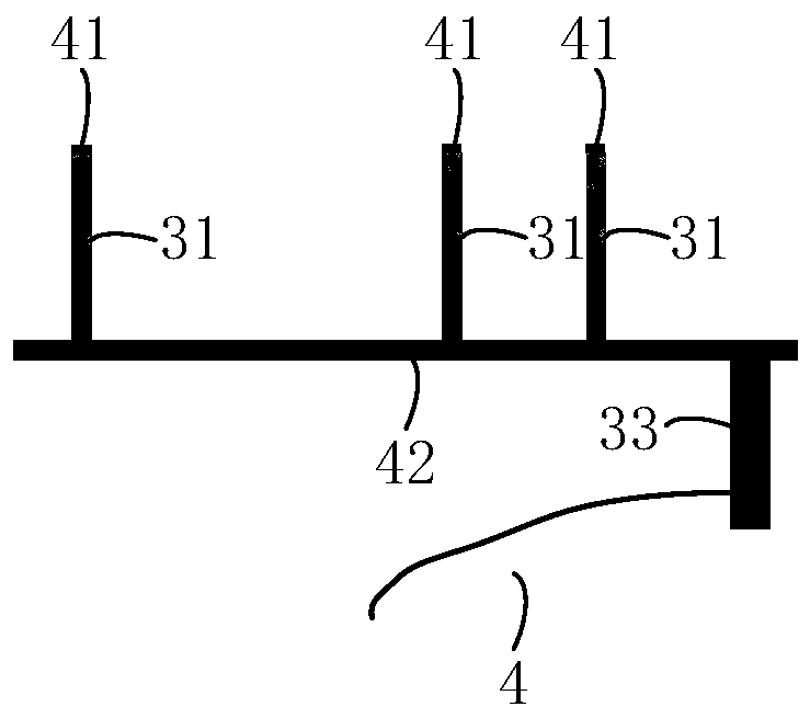
[0034] like figure 1 and figure 2 As shown, three support members 31 are passed through the base 2, and the top thereof is used to carry the wafer 100. The three support members 31 can be raised and lowered relative to the base 2 to carry and drive the wafer 100 to be selectively located in multiple locations. Station. The driving part 32 specifically adopts a servo motor or a stepping motor, and the driving part 32 is arranged on the outside of the chamber 1, and is connected with a plurality of supports 31 through a drive link 33 to drive the plurality of supports 31 to rise and fall, while the drive link 33 33 may specifically be a lead screw structure. In actual application, under the control of the controller 5 , the driving part 32 drives the multiple supports 31 to move up and down between the multiple stations through the drive link 33 , thereby driving the wafer 100 to move between the multiple stations. , and further realize the heating of the wafer 100 in multiple temperature intervals. With the above design, since the motion position accuracy of the servo motor or stepping motor is very accurate, the motion position of multiple supports is also relatively accurate, so that the temperature of the wafer 100 can be precisely controlled; and because the driving part is arranged in the chamber 1, it can also effectively reduce application and maintenance costs.
[0035] It should be noted that the embodiment of the present application does not limit the specific types of the driving part 32 and the driving link 33 , for example, the driving part 32 can adopt other types of drivers as long as it achieves the same precision as the servo motor. Therefore, the embodiment of the present application is not limited thereto, and those skilled in the art can adjust the setting by themselves according to the actual situation.
[0036] In one embodiment of this application, as figure 1 and figure 2 As shown, the temperature measurement assembly 4 includes a plurality of temperature sensors 41 corresponding to the support members 31 one by one. Specifically, a plurality of temperature sensors 41 are respectively disposed on the tops of the plurality of supports 31 , and the temperature sensors 41 are located between the tops of the supports 31 and the wafer 100 . Optionally, the temperature sensor 41 is a contact temperature sensor 41 . The temperature sensor 41 can be a thermocouple, which is directly arranged on the top of the support 31 , the wire 42 of the thermocouple can pass through the support 31 , and the wire 42 can pass through the base 2 and lead to the outside of the chamber 1 . Due to the use of the contact temperature sensor 41, not only the temperature on the surface of the wafer 100 can be accurately monitored, and other interference factors can be reduced, thereby effectively improving the accuracy of the measured temperature value; and because the contact temperature sensor 41 has a low cost and a simple structure, It can greatly reduce the failure rate while reducing the application cost.
[0037] It should be noted that the embodiment of the present application does not limit the type of the temperature sensor 41 , for example, the temperature sensor 41 may also be an infrared temperature sensor, which may be disposed inside the support member 31 or in other positions of the chamber 1 . Therefore, the embodiment of the present application is not limited thereto, and those skilled in the art can adjust the setting by themselves according to the actual situation.
[0038] In one embodiment of this application, as figure 1 As shown, the distance between any two adjacent stations is set corresponding to the minimum resolution of the servo motor or stepper motor. Specifically, the distance between any two adjacent stations is set corresponding to the minimum drive amount of the servo motor or stepper motor. In other words, the servo motor or stepper motor can drive the support to move with a small distance, thus, Under the control of the controller 5 , the drive unit 32 enables multiple stations to correspond to multiple smaller temperature ranges.
[0039] In one embodiment of this application, as figure 1 As shown, the semiconductor processing equipment further includes a pipeline 6 connected to the chamber 1 , and a valve 61 is arranged on the pipeline 6 , and the valve 61 is used to control the input of cooling gas into the chamber 1 through the pipeline 6 . The pipeline 6 is arranged between the chamber 1 and the gas source 62, and the pipeline 6 is also provided with a valve 61, the valve 61 can selectively conduct the gas source 62 and the chamber 1, so as to control the input of cooling gas into the chamber 1 through the pipeline 6 Inside. Optionally, the semiconductor processing equipment may further include an air extraction pump 7 for evacuating the chamber 1 and exhausting cooling gas and waste gas in the chamber 1 . Optionally, a uniform flow plate 8 is provided on the top of the chamber 1 , and the cooling gas flows evenly through the uniform flow plate 8 to the base 2 and the wafer 100 carried on the base 2 to perform process steps.
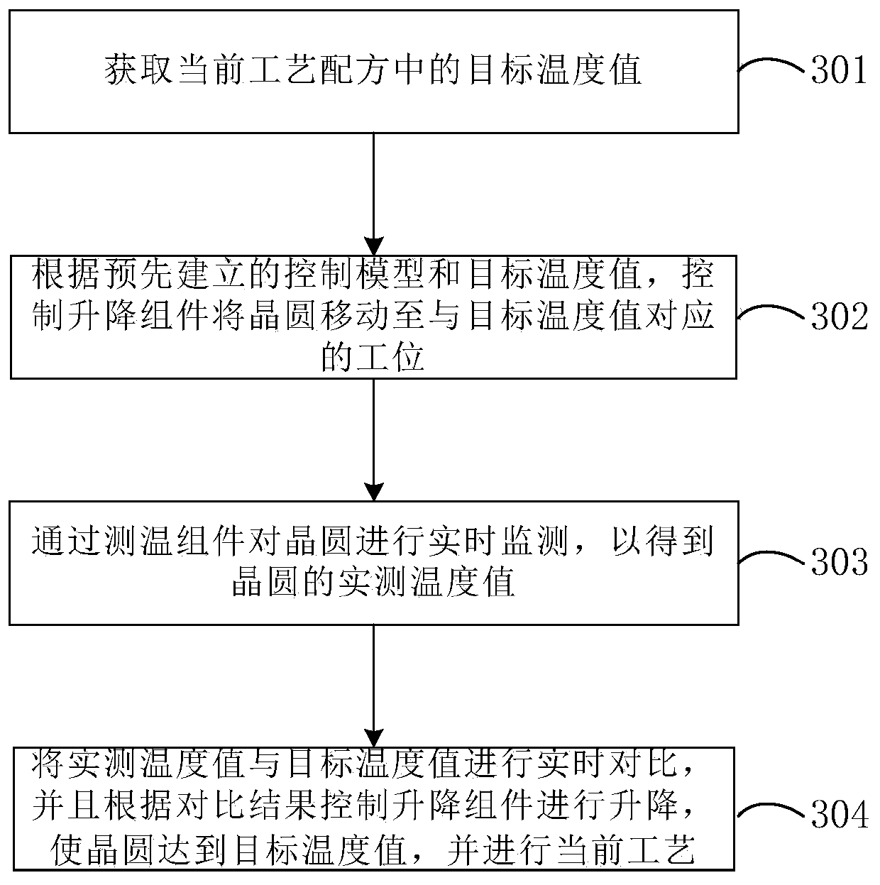
[0040] Based on the same inventive concept, the embodiment of the present application provides a process control method for semiconductor processing equipment as provided in the above embodiments. The schematic flow chart of the method is as follows image 3 As shown, the method includes:
[0041] S301: Obtain the target temperature value in the current process recipe.
[0042] S302: According to the pre-established control model and the target temperature value, control the lifting component to move the wafer to the station corresponding to the target temperature value.
[0043] S303: Monitor the wafer in real time through the temperature measuring component to obtain the actual temperature value of the wafer.
[0044] S304: Compare the measured temperature value with the target temperature value in real time, and control the lifting component to lift according to the comparison result, so that the wafer reaches the target temperature value, and perform the current process.
[0045] Optionally, if the measured temperature value is greater than the target temperature value, the lifting assembly is controlled to rise; if the measured temperature value is less than the target temperature value, the lifting assembly 3 is controlled to descend; Change.
[0046] Optionally, after the lifting assembly is controlled to rise, if the wafer reaches the station farthest from the upper surface of the base among the plurality of stations, and the measured temperature value is still greater than the target temperature value, the cooling gas is controlled to be input into the chamber until The measured temperature value is equal to the target temperature value.
[0047] like Figure 1 to Figure 3 As shown, the method for controlling semiconductor processing equipment will be described below through a specific implementation manner.
[0048] Specifically, the driving part 32 can drive the three support members 31 to move with a small distance. When the three support members 31 are at different heights, the heat radiation of the base 2 to the wafer 100 is different, so that the wafer 100 can be stabilized at different heights. temperature range. When it is necessary to perform a deglue process on the wafer 100 , the manipulator puts the wafer 100 on the three supports 31 , the manipulator retracts into the chamber 1 and closes the gate valve of the chamber 1 . The temperature sensors 41 on the three supports 31 read the initial temperature of the wafer 100, and the controller 5 can obtain the target temperature value of the deglue process step from the current process formula, and the controller 5 controls the driving part 32 to drive the three wafers according to the target temperature value. Each support member 31 moves to the corresponding station for heating, and the deglue process step can be started after the wafer 100 reaches the target temperature value.
[0049] In order to facilitate the understanding of the embodiments of the present application, the calculation method of the control model for the correspondence between multiple stations and the target temperature value is described as follows: the wafer 100 is obtained at different heights of the three supports 31 by the experimental wafer 100 For temperature curve, please refer to Figure 4 As shown, the maximum temperature value is that the three support members 31 drive the wafer 100 directly onto the upper surface 21 of the susceptor 2 , so the wafer 100 can reach the same temperature as the susceptor 2 . The initial temperature is the temperature value when the manipulator puts the wafer 100 into the chamber 1 and the three supports 31 are at the highest positions. The wafer 100 moves toward the base 2 on the three supports 31 with the minimum driving amount of the servo motor (ie, the minimum resolution of the servo motor), that is, the three supports 31 move to the next station, and each movement of a minimum drive After the temperature of the wafer 100 is stabilized, the controller 5 records the temperature, and the temperature curve obtained when the wafer 100 moves to the upper surface 21 of the susceptor 2 .
[0050] After that, the experimental data is analyzed by the simulation algorithm software, and the matrix data is fitted to obtain the relationship fitting function corresponding to the relationship between the input (height L of the three supports) and the output (wafer temperature T).
[0051] The following relationship fitting function is obtained by automatically collecting data:
[0052] T=-7E-06L 6 +0.0008L 5 -0.0362L 4 +0.7341L 3 -6.7642L 2 +14.61L+24
[0053] 1.27
[0054] The value range of T: 250≤T≤44°C; the value range of L: 0≤L≤45mm (millimeters), of which 250°C can be changed according to the maximum temperature used in the process steps, and 44°C is the initial value of wafer 100 The average value placed on the three supports.
[0055] Through the above experiment process, the realization of controlling the temperature of the wafer 100 is completed. Through the specific performance of the experiment in the later stage, the relationship fitting function is modified as needed, so as to more accurately adapt to the accuracy of the target temperature value during the actual execution process. control. However, it should be noted that the above relationship fitting function is only an example of the control model, and those skilled in the art can adjust the setting according to the actual situation in practical applications.
[0056] For example, when the degumming process step starts, the controller 5 reads the target temperature value of the degumming process step in the process recipe, and the three support members 31 move to the stations corresponding to the preset temperature, and the temperature of the temperature measuring component 4 The sensor 41 monitors the wafer 100 in real time to obtain the measured temperature value, and compares the measured temperature value with the target temperature value in real time, so as to control the lifting state of the lifting assembly 3 according to the comparison result. Specifically, when the measured temperature value is greater than the target temperature value, the controller 5 can control the lifting assembly 3 to rise by one station so that the wafer 100 is heated up to the target temperature value; when the measured temperature value is less than the target temperature value, the controller 5 The lifting assembly 3 can be controlled to descend by one station so that the wafer is cooled to the target temperature value; and when the measured temperature value is equal to the target temperature value, the lifting assembly 3 is controlled to maintain the existing station, and the glue removal process step can be started. Further, when the wafer reaches the station farthest from the upper surface 21 of the susceptor 2 among the plurality of stations, and the measured temperature value is still greater than the target temperature value, the cooling gas is controlled to be input into the chamber until the measured temperature value is equal to the target temperature value temperature value.
[0057]Optionally, after the deglue process steps are completed, the controller 5 can judge whether there are other processes, if there are other processes, then use other processes as the current process, and repeat steps S301 to S304 until all processes are completed .
[0058] In the embodiment of the present application, the lifting component carries and drives the wafer to move up and down relative to the base, so as to drive the wafer to move between multiple stations. Since the multiple stations correspond to different target temperature values, it is realized according to different types The purpose of adjusting the target temperature value of different wafers and different processes, and can also meet the demand for temperature changes during the process, thus not only effectively improving the yield of wafer processing, but also greatly improving process efficiency. Since the temperature measurement component collects the measured temperature value of the wafer in real time, real-time monitoring of the wafer temperature can be realized, thereby effectively improving the accuracy of the wafer temperature. On the other hand, since the temperature requirements of different wafers and different processes are met, the scope of application of the embodiments of the present application is greatly improved.
[0059] By applying the embodiment of the present application, at least the following beneficial effects can be achieved:
[0060] In the embodiment of the present application, according to the pre-established control model and the obtained target temperature value in the current process recipe, the lifting assembly is controlled to move the wafer to the station corresponding to the target temperature value, so that the wafer can quickly reach the target temperature value, and then monitor the wafer in real time through the temperature measurement component, and control the lifting component to lift according to the comparison result between the measured temperature value and the target temperature value, so that the wafer can accurately reach the target temperature value. It can be seen that this implementation For example, the wafer can reach the target temperature value quickly and accurately.
[0061] It can be understood that, the above embodiments are only exemplary embodiments adopted for illustrating the principle of the present invention, but the present invention is not limited thereto. For those skilled in the art, various modifications and improvements can be made without departing from the spirit and essence of the present invention, and these modifications and improvements are also regarded as the protection scope of the present invention.
[0062] Those skilled in the art can understand that the various operations, methods, and steps, measures, and schemes in the processes that have been discussed in this application can be replaced, changed, combined, or deleted. Furthermore, the various operations, methods, and other steps, measures, and schemes in the processes that have been discussed in this application may also be replaced, changed, rearranged, decomposed, combined, or deleted. Further, steps, measures, and schemes in the prior art that have operations, methods, and processes disclosed in the present application may also be alternated, changed, rearranged, decomposed, combined, or deleted.
[0063] In the description of this application, it should be noted that unless otherwise specified and limited, the terms "installation", "connection", and "connection" should be understood in a broad sense, for example, it can be a fixed connection or a detachable connection. Connected, or integrally connected; it can be directly connected, or indirectly connected through an intermediary, and it can be the internal communication of two elements. Those of ordinary skill in the art can understand the specific meanings of the above terms in the present invention in specific situations.
[0064] The above descriptions are only some implementations of the present application. It should be pointed out that for those of ordinary skill in the art, some improvements and modifications can be made without departing from the principle of the application. These improvements and modifications are also It should be regarded as the protection scope of this application.