Relay coil-based arbitrary constant-voltage wireless power transmission compensation network and compensation method

A technology of wireless power transmission and relay coils, which is applied to electrical components, circuit devices, etc., can solve problems such as poor output voltage stabilization characteristics, compensation network detuning, and increase in the number of devices to achieve good output characteristics and reduce capacity.

Pending Publication Date: 2020-08-04
FUZHOU UNIV
View PDF0 Cites 6 Cited by
  • Summary
  • Abstract
  • Description
  • Claims
  • Application Information

AI Technical Summary

Problems solved by technology

But this kind of compensation method, first, the output characteristics of the load are determined by the entire magnetic coupling system, and the internal reactance of the system cannot be fully compensated, and the output voltage stabilization characteristics are poor
Second, there are three resonant frequencies in the magnetic coupling system with relay coils in the application, which is more prone to compensation network detuning problems than the two-coil system without relay coils
But this kind of compensation method, first, the output characteristics of the load are determined by the entire magnetic coupling system, and the

Method used


Image

  • Relay coil-based arbitrary constant-voltage wireless power transmission compensation network and compensation method
  • Relay coil-based arbitrary constant-voltage wireless power transmission compensation network and compensation method
  • Relay coil-based arbitrary constant-voltage wireless power transmission compensation network and compensation method

Examples


Embodiment Construction

[0068] The technical solution of the present invention will be specifically described below in conjunction with the accompanying drawings.

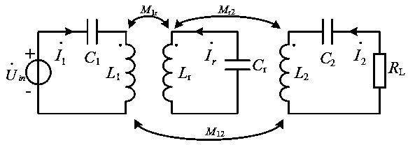
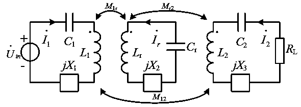
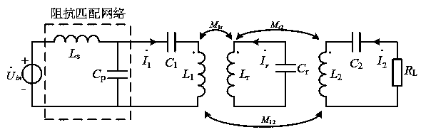
[0069] Such as Figure 11 As shown, the present invention provides an arbitrary constant-voltage wireless power transmission compensation network based on relay coils, adding parallel compensation capacitors on the basis of maintaining the original compensation network structure, so that the system can obtain different levels of constant-voltage output characteristics and reduce the inverse The capacity of the transformer; specifically, it includes a transmitting coil circuit, a relay coil circuit, and a receiving coil circuit. The transmitting coil circuit includes a voltage source connected in series, a transmitting coil, and a compensation capacitor for the transmitting coil circuit. The relay coil and the relay coil circuit compensation capacitor, the receiving coil circuit includes the receiving coil, the receiving coil circuit serie...


PUM


Abstract

The invention relates to a relay coil-based arbitrary constant-voltage wireless power transmission compensation network and compensation method. The relay coil-based arbitrary constant-voltage wireless power transmission compensation network comprises a transmitting coil loop, a relay coil loop and a receiving coil loop. The transmitting coil loop comprises a voltage source, a transmitting coil and a transmitting coil loop compensation capacitor which are connected in series; the relay coil loop comprises a relay coil and a relay coil loop compensation capacitor which are connected in series;and the receiving coil loop comprises a receiving coil, a receiving coil loop series compensation capacitor, a receiving coil loop parallel compensation capacitor and a load. According to the invention, the parallel compensation capacitor is added on the basis of maintaining an original compensation network structure, and the design of the compensation parameters enables the system to obtain different levels of constant voltage output characteristics and effectively reduce the capacity of the inverter, and the problem of detuning is not easy to occur compared with a traditional three-coil structure.

Description

technical field [0001] The invention relates to a compensation network and a compensation method for arbitrary constant voltage wireless power transmission based on relay coils. Background technique [0002] With the rapid development of the electric vehicle industry, people have put forward higher requirements for the safety and convenience of the charging system. Therefore, the contactless charging system of electric vehicles has also been more and more widely used. When the transmission distance increases, the transmission efficiency of the wireless power transmission system decreases rapidly. To solve this problem, inserting a relay coil between the transmitting coil and the receiving coil is a simple, easy, cost-effective and effective way to increase the wireless energy transmission distance. [0003] The existence of the relay coil acts as an energy transfer station, but there are multiple power transmission paths in the system, which makes the compensation network ...

Claims


Application Information

Patent Timeline
IPC IPC(8): H02J50/12H02J50/50
CPCH02J50/12H02J50/50
Inventor 陈庆彬杨丰钢陈为
Owner FUZHOU UNIV
Why Eureka
Try Eureka