Non-jet normal-pressure thermal plasma generator

A technology of plasma generator and atmospheric pressure heating, which is applied in the field of plasma, can solve the problems of material utilization, processing efficiency and processing effect, unstable operation, and low power limit.

Pending Publication Date: 2020-08-04
SICHUAN HOT PULSE MICROWAVE SCI & TECH CO LTD
View PDF1 Cites 1 Cited by
  • Summary
  • Abstract
  • Description
  • Claims
  • Application Information

AI Technical Summary

Problems solved by technology

However, a large amount of auxiliary gas is required to effectively confine and orient the plasma, and a large amount of gas to be treated cannot pass through the plasma region and cannot produce effective reactions; and the gas passing through the plasma region may have adverse side reactions due to excessive temperature, making the Material utilization, processing efficiency and processing effect have all become poorer
In addition, if the microwave power is too large and the plasma temperature and concentration are too high, it will be difficult for the auxiliary gas to reliably confine the plasma and form a jet, which will eventually lead to unstable operation or damage to the device
Moreover, the addition of a large amount of auxiliary gas not only increases the processing burden of the microwave plasma device, but also increases the separation burden of subsequent devices, and also reduces the reaction efficiency.
In addition, because the plasma start-up area of ​​this type of device is the same area as the subsequent continuous work area, the microwave power density in the work area is very high during low-power operation. If a high-power plasma device is required, the microwave power density in the work area, plasma The body temperature and concentration will be extremely high. At this time, limited by the microwave transmission system structure and heat dissipation, the microwave power that can be loaded is small and the upper limit of the power is low, which is greatly limited. For industrial applications, tens of kilowatts, hundreds of kilowatts, The long-term continuous application of the kilowatt level is still unsatisfactory

Method used


Image

  • Non-jet normal-pressure thermal plasma generator
  • Non-jet normal-pressure thermal plasma generator

Examples


Embodiment 1

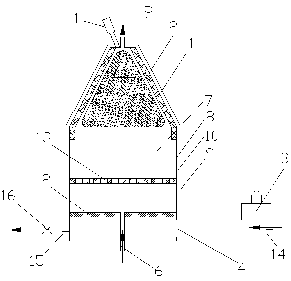
[0041] A non-jet flow atmospheric pressure thermal plasma generator, including an igniter 1 and a microwave source 3, and also includes a reaction chamber, on which a gas channel I5 and a gas channel II6 are opened, and the reaction chamber includes a cylindrical cavity 7 and the tapered chamber 2 located above the cylindrical chamber 7, the tapered chamber 2 communicates with the cylindrical chamber 7, the cylindrical chamber 7 has a microwave feeding port 4, and the microwave source 3 is connected to the microwave feeding port 4 , the igniter 1 is connected to the conical cavity 2 .

[0042] This embodiment is the most basic implementation mode. There are gas channel I and gas channel II on the reaction chamber. The reaction chamber includes a cylindrical chamber and a conical chamber located above the cylindrical chamber. The conical chamber communicates with the cylindrical chamber. , There is a microwave feed port on the cylindrical cavity, the microwave source is connect...

Embodiment 2

[0044] A non-jet flow atmospheric pressure thermal plasma generator, including an igniter 1 and a microwave source 3, and also includes a reaction chamber, on which a gas channel I5 and a gas channel II6 are opened, and the reaction chamber includes a cylindrical cavity 7 and the tapered chamber 2 located above the cylindrical chamber 7, the tapered chamber 2 communicates with the cylindrical chamber 7, the cylindrical chamber 7 has a microwave feeding port 4, and the microwave source 3 is connected to the microwave feeding port 4 , the igniter 1 is connected to the conical cavity 2 .

[0045] The reaction chamber is a double-layer metal structure, including an inner chamber 8 and an outer chamber 9, and an interlayer 10 for introducing a fluid medium is formed between the inner chamber 8 and the outer chamber 9.

[0046] The inner wall of the inner cavity body 8 of the tapered cavity 2 is lined with a thermal insulation layer 11, and the thickness of the thermal insulation la...

Embodiment 3

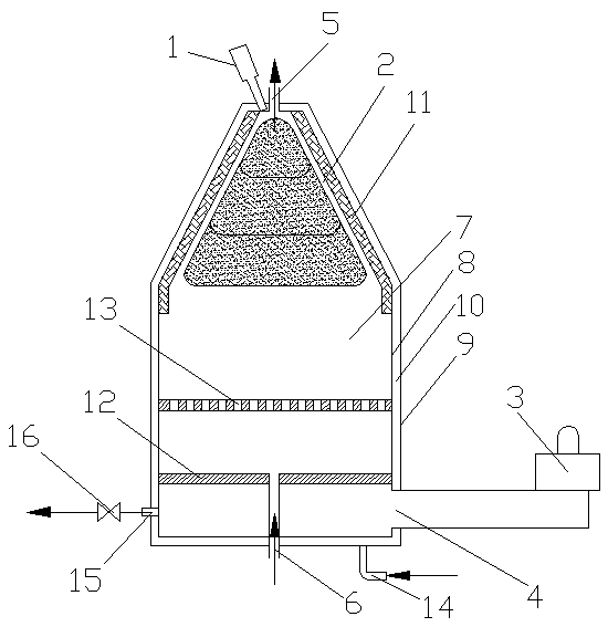
[0051] A non-jet flow atmospheric pressure thermal plasma generator, including an igniter 1 and a microwave source 3, and also includes a reaction chamber, on which a gas channel I5 and a gas channel II6 are opened, and the reaction chamber includes a cylindrical cavity 7 and the tapered chamber 2 located above the cylindrical chamber 7, the tapered chamber 2 communicates with the cylindrical chamber 7, the cylindrical chamber 7 has a microwave feeding port 4, and the microwave source 3 is connected to the microwave feeding port 4 , the igniter 1 is connected to the conical cavity 2 .

[0052] The reaction chamber is a double-layer metal structure, including an inner chamber 8 and an outer chamber 9, and an interlayer 10 for introducing a fluid medium is formed between the inner chamber 8 and the outer chamber 9.

[0053] The inner wall of the inner cavity body 8 of the tapered cavity 2 is lined with a thermal insulation layer 11, and the thickness of the thermal insulation la...


PUM


Abstract

The invention discloses a non-jet normal-pressure thermal plasma generator, and belongs to the technical field of microwave plasmas. The non-jet normal-pressure thermal plasma generator comprises an igniter and a microwave source, and is characterized by further comprising a reaction cavity; a gas channel I and a gas channel II are formed in the reaction cavity; the reaction cavity comprises a cylindrical cavity and a conical cavity located above the cylindrical cavity, wherein the conical cavity is communicated with the cylindrical cavity; a microwave feed port is formed in the cylindrical cavity; the microwave source is connected with the microwave feed port; and the igniter is connected to the conical cavity. According to the invention, large and uniform thermal plasmas can be formed, so that the gas to be treated is fully and uniformly heated, and the reaction efficiency is improved; uniform distribution in a set space range is realized, destructive breakdown discharge can be effectively prevented, and heat dissipation balance is easy to control; and reasonable temperature, stable structure and long-term operation stability of the whole generator are ensured under the conditionof reducing heat dissipation as much as possible.

Description

technical field [0001] The invention relates to the technical field of microwave plasma, in particular to a non-jet flow atmospheric pressure thermal plasma generator. Background technique [0002] Plasma is the fourth state of matter. It usually refers to ionized or partially ionized conductive gas, which includes six typical particles: electrons, positive ions, negative ions, atoms or molecules in the excited state, and atoms or molecules in the ground state. molecules and photons. Whether it is partially ionized or completely ionized; the total number of negative charges in it is equal to the total number of positive charges, so it is called plasma, which is electrically neutral as a whole in the time and space of the macro scale. A stricter definition is: Plasma is a collection of electrons, positive ions and neutral particles that is electrically neutral as a whole. Plasma is divided into two categories according to temperature: high-temperature plasma and low-tempera...

Claims


Application Information

Patent Timeline
Patent Type & Authority Applications(China)
IPC IPC(8): H05H1/30
CPCH05H1/30
Inventor 周川刘毅李天平
Owner SICHUAN HOT PULSE MICROWAVE SCI & TECH CO LTD
Why Eureka
Try Eureka