Static-state double-classification powder concentrator and semi-finished pre-grinding system

A powder classifier, static technology, applied in the field of cement semi-final pre-grinding process, can solve the problems that the particle size of the powder classifier cannot be adjusted, affects the stable production control, and the sieve holes are easy to block, so as to reduce construction investment and production operation Effects of cost, ease of promotion, and simplification of device operation control

Pending Publication Date: 2020-08-07
NANJING TECH UNIV
View PDF2 Cites 6 Cited by
  • Summary
  • Abstract
  • Description
  • Claims
  • Application Information

AI Technical Summary

Problems solved by technology

The process of the system is simple, but because it does not use airflow air separation, there are some disadvantages: it needs to use a super-sized sieve to meet the production requirements, and the powder selection efficiency is low; at the same time, because the sieve holes are fixed, the powder selection during the production process The diameter cannot be adjusted; in addition, the sieve hole is easy to be blocked; the sieve is easy to wear; the change of the pore diameter after the sieve wears directly affects the production stability control

Method used


Image

  • Static-state double-classification powder concentrator and semi-finished pre-grinding system
  • Static-state double-classification powder concentrator and semi-finished pre-grinding system
  • Static-state double-classification powder concentrator and semi-finished pre-grinding system

Examples


Embodiment Construction

[0024] In order to make the object, technical solution and advantages of the present invention clearer, the present invention will be further described in detail below in conjunction with the accompanying drawings and embodiments. It should be understood that the specific embodiments described here are only used to explain the present invention, not to limit the present invention.

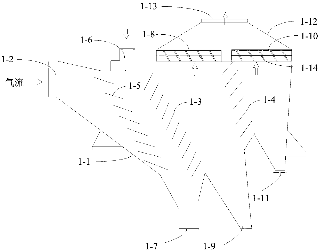
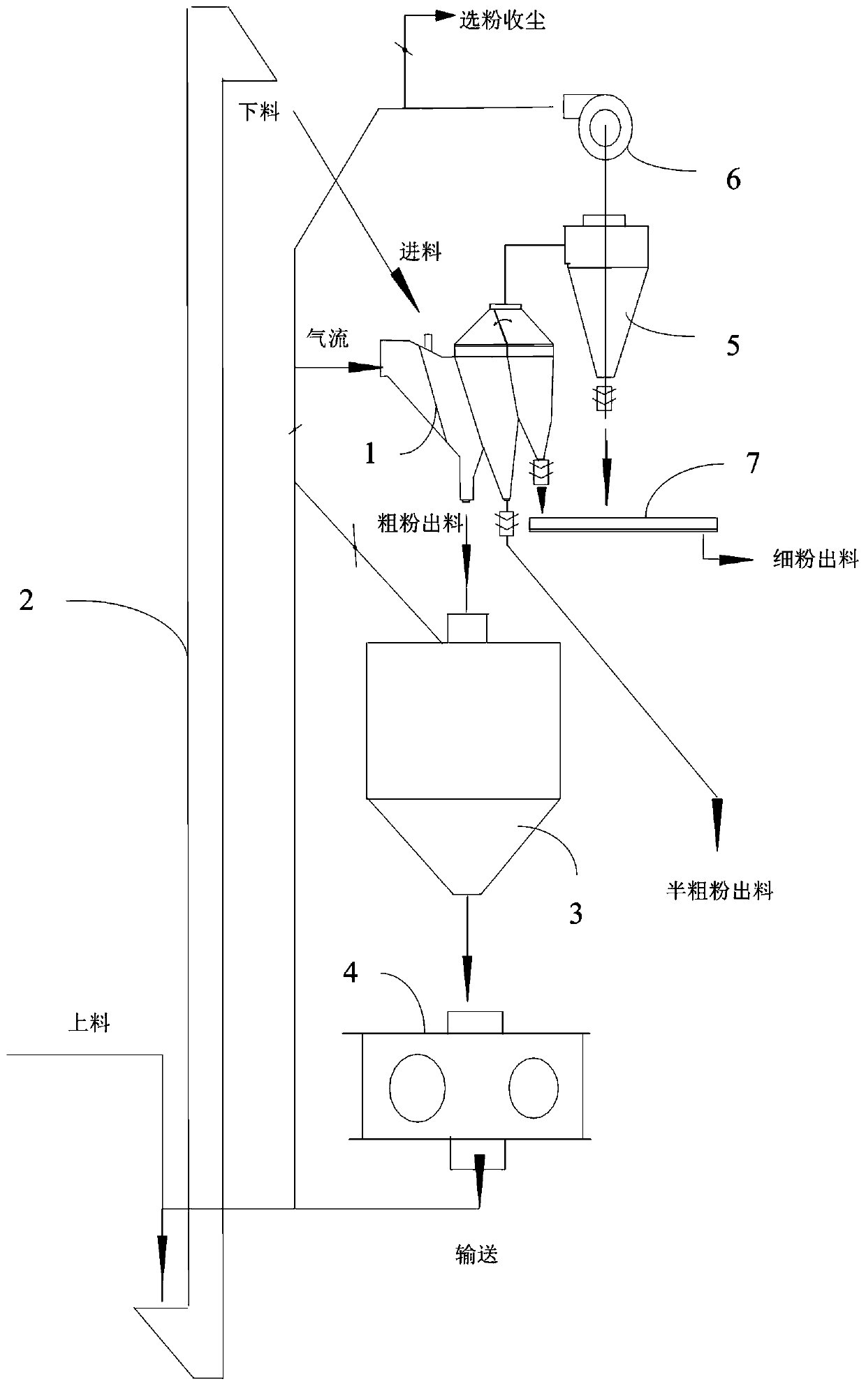
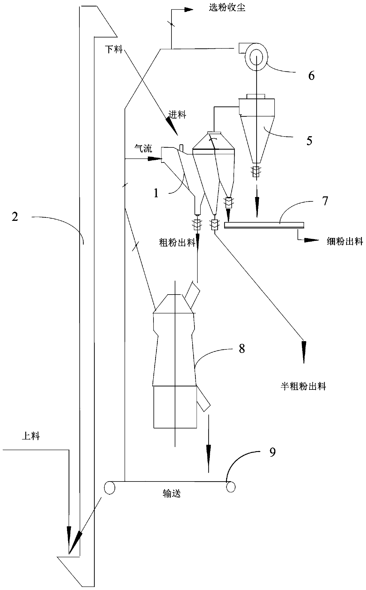
[0025] like Figure 1~3 As shown, among them, figure 1 It is a schematic diagram of the internal structure of an embodiment of the static double-class powder separator of the present invention; figure 2 It is a structural schematic diagram of an embodiment of the semi-final pre-grinding system of the cement roller press of the present invention; image 3 It is a structural schematic diagram of an embodiment of the external circulation semi-final pre-grinding system of the cement vertical mill of the present invention.

[0026] The invention discloses a static double-classification powder separa...


PUM


Abstract

The invention discloses a static-state double-classification powder concentrator and a semi-finished pre-grinding system. According to the static-state double-classification powder concentrator, an air inlet is arranged at the position, close to the top, of the side face of a shell, and the shell is internally divided by a coarse material guiding baffle set and a fine powder guiding baffle set into a coarse material sieving cavity, a semi-coarse material sieving cavity and a fine powder sieving cavity. The coarse material sieving cavity is internally provided with a material slide carriage setwith the top inclining towards the air inlet. The part, above the material slide carriage set, of the shell is provided with a feed port, and the part, below the material slide carriage set, of the shell is provided with a coarse powder outlet. The part, above the semi-coarse material sieving cavity, of the shell is provided with a first air outlet, and the part, below the semi-coarse material sieving cavity, of the shell is provided with a semi-coarse powder outlet. The part, above the fine powder sieving cavity, of the shell is provided with a second air outlet, and the part, below the finepowder sieving cavity, of the shell is provided with a fine powder outlet. The size of the first air outlet and the size of the second air outlet are controlled through valves. The powder concentrator can be applied to various pre-grinding systems. According to the powder concentrator, an existing v-shaped powder concentrator can be directly improved, and coarse particles, semi-coarse particles and fine powder finished products in materials can be efficiently separated.

Description

technical field [0001] The invention belongs to the cement semi-final pre-grinding process technology, and in particular relates to a static double-grading powder separator, a cement roller press semi-final pre-grinding system and a cement vertical mill external circulation semi-final pre-grinding system. Background technique [0002] At present, the cement industry widely adopts roller press pre-grinding and ball mill to form a combined grinding system to grind cement clinker and other materials. The materials that need to be ground are squeezed by the roller press and fed by the lifting conveyor mechanism. The V-type powder classifier breaks up and sorts, the coarse material falls into the load bin above the roller press, and then is fed to the roller press for extrusion, and the fine material is brought into the cyclone dust collector and collected as a semi-finished product to be fed to the ball mill for further processing. Grinding: The materials exiting the ball mill a...

Claims


Application Information

Patent Timeline
Patent Type & Authority Applications(China)
IPC IPC(8): B02C21/00B02C23/18B02C23/22
CPCB02C21/00B02C23/18B02C23/22
Inventor 陈文平
Owner NANJING TECH UNIV
Why Eureka
Try Eureka