Protection structure for high and steep slope and construction method thereof

A technology for protective structures and high and steep slopes, which can be used in basic structure engineering, excavation, construction, etc. It can solve the problems of difficulty in forming effective connections of prefabricated beams, difficulty in transporting concrete on site, and poor concrete tamping effect, etc., to achieve high construction efficiency , easy to implement, good seismic effect

Inactive Publication Date: 2020-08-07
CHINA RAILWAY ERYUAN ENG GRP CO LTD
View PDF5 Cites 1 Cited by
  • Summary
  • Abstract
  • Description
  • Claims
  • Application Information

AI Technical Summary

Problems solved by technology

[0009] The purpose of the present invention is to overcome existing in the prior art, when traditional anchor concrete frame beam is applied to high and steep slope protection, on-site concrete transportation is difficult; Prefabricated beam is difficult to form the ground beam of effective connection; Destruction of the ecological environment; Poor concrete tamping effect when concrete frame beams are poured; Poor seismic capacity. Provide a protective structure and construction method for high and steep slopes. The anchoring force of the anchoring device acts on the truss beam structure. The slope surface of the high and steep slope is used to protect the high and steep slope, avoiding the difficulty of concrete transportation and the poor effect of pouring and compacting on site, and the truss beam structure can be assembled on site through a single member, which is not only reliable in quality, but also Compared with concrete beams, it greatly facilitates transportation and reduces construction costs

Method used


Image

  • Protection structure for high and steep slope and construction method thereof
  • Protection structure for high and steep slope and construction method thereof
  • Protection structure for high and steep slope and construction method thereof

Examples


Embodiment 1

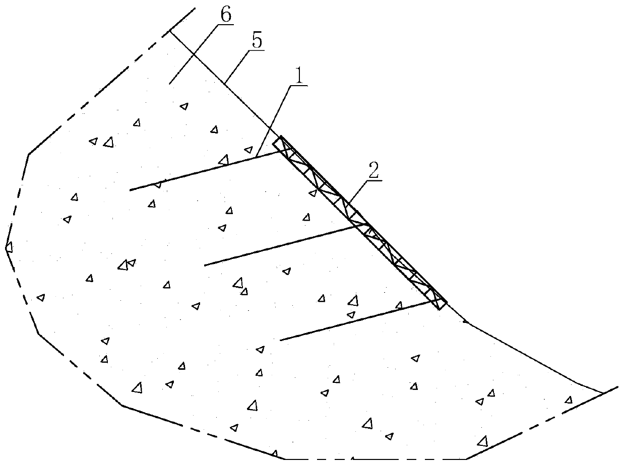
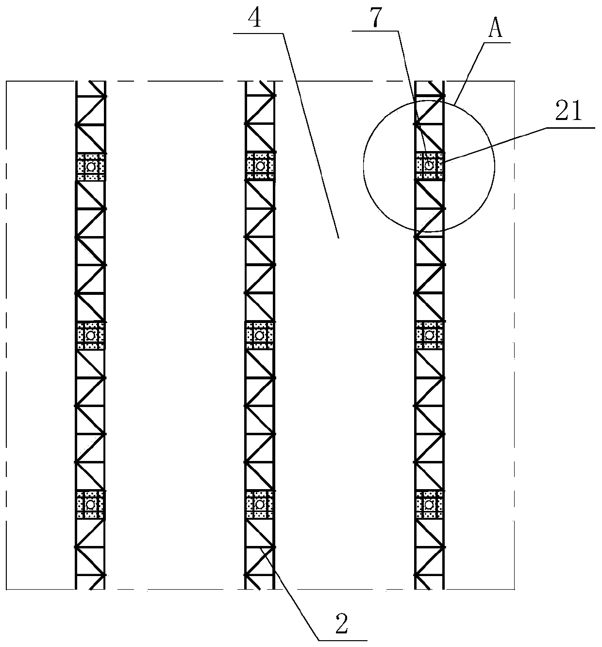
[0061] Such as Figure 1-4 As shown in and 8, a high and steep protective structure for high and steep slopes described in this embodiment includes inclined anchor cables 71 and truss steel beams 2, and truss steel beams are arranged at intervals along the slope surface 5 of the high and steep slope 6 The beam 2; the inclined anchor cable 71 is anchored into the slope body of the slope 6 at equal intervals along the high and steep slope 6; ; Plant slope protection 4 is set in the slope of two adjacent truss steel beams 2 .

[0062] In the above solution: the inclined anchor cable 71 is: at least a part of the anchor cable is anchored on the side slope 6 but not perpendicular to the slope surface 5 .

[0063] The truss steel beams 2 are embedded in the surface of the high and steep slope 6; the truss steel beams 2 are assembled on site, and the truss steel beams 2 are arranged in parallel at equal intervals on the slope 6; After the truss steel beam 2 is installed, the tamped...

Embodiment 2

[0073] Such as Figure 1-4 Shown in and 8, a kind of construction method described in the present embodiment is used to form a kind of high and steep protective structure for the high and steep slope described in embodiment 1, this method comprises the following steps:

[0074] ①. Determine the hole position of the inclined anchor cable 71, drill into the hole with a drilling rig, install and grout the inclined anchor cable 71;

[0075] ②. After the construction of the inclined anchor cable 71 on the slope surface is completed, the position of the truss steel beam 2 is positioned and the groove is cut;

[0076] ③. Assemble the truss steel beam 2 while transporting the rods;

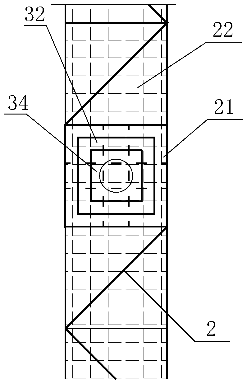
[0077] ④. Pass the inclined anchor cable 71 steel strand through the center of the well-shaped composite member through the wedge-shaped seat 32, and weld and fix the bottom surface of the wedge-shaped seat 32 to the well-shaped composite member;

[0078] ⑤. Put the jack base on the top surface of the w...

Embodiment 3

[0083] Such as figure 1 , 5 , 6, 7 and 8, the protective structure for high and steep slopes described in this embodiment differs from Embodiment 1 or 2 in that it includes a frame truss structure and inclined anchor cables 71, along The truss steel girders 2 and truss beams 33 are arranged at intervals on the slope surface of the high and steep slope 6 to form a frame truss structure; inclined anchor cables 71 are obliquely anchored into the slope body of the slope 6; wedge-shaped seat 32, anchorage 31, and bucket-shaped steel plate head 34 are sequentially arranged on the intersection joints of the truss steel beam 2 and the truss beam 33;

[0084] In the above scenario:

[0085]The truss steel beam 2 and the truss beam 33 are embedded in the surface of the high and steep slope 6; The lattice layout is square or rhombus; after the truss steel beam 2 and truss beam 33 are installed, the gaps are backfilled with excavated soil; in the slope 6 in a corrosive environment, the...


PUM


Abstract

The invention relates to the technical field of geotechnical engineering, in particular to a protection structure for a high and steep slope and a construction method thereof. The protection structurecomprises at least two truss steel beams which are arranged along the slope surface of the side slope at intervals, the truss steel beams are connected with prestresse anchoring devices, and one ends, far away from the truss steel beams, of the prestress anchoring devices are anchored into the side slope. According to the protection structure for the high and steep slope, the truss steel beams are connected and fixed to the slope surface of the slope through the prestress anchoring devices so as to achieve the purpose of protecting the high and steep slope, the truss steel beams can be assembled through single rod pieces on site, and therefore the problems that concrete is difficult to transport and the cast-in-situ tamping effect is poor are solved, and the the quality is reliable; and compared with concrete connecting beams, transportation is greatly facilitated, and the construction cost is reduced, so that the anti-seismic property is better.

Description

technical field [0001] The invention relates to the technical field of geotechnical engineering, in particular to a protective structure for high and steep slopes and a construction method thereof. Background technique [0002] In order to serve Tibet's economic construction and meet the national strategic needs, planning and construction of railways and highways into Tibet are being implemented in an orderly manner, and the Sichuan-Tibet Railway is one of them. However, the high mountains and deep valleys along the Sichuan-Tibet Railway have the characteristics of high intensity, high altitude, and large height difference. High and steep natural slopes are widely distributed along the line, with the height reaching the kilometer level and the slope reaching 60°. Influenced by structures, etc., a large number of unstable slopes or dangerous rock masses are distributed on high and steep natural slopes, which are very easy to lose stability and slide under the action of earthq...

Claims


Application Information

Patent Timeline
Patent Type & Authority Applications(China)
IPC IPC(8): E02D17/20E02D5/74
CPCE02D5/74E02D17/20
Inventor 陈伟志郭在旭姚裕春龙礼斌韩想平
Owner CHINA RAILWAY ERYUAN ENG GRP CO LTD
Why Eureka
Try Eureka